
Parking pilot system and method

a pilot system and parking technology, applied in the field of parking pilot system, can solve the problems of unqualified drivers, inexperienced drivers still have to determine whether the parking area is safe, and it is difficult for unskilled drivers to park their vehicles

Active Publication Date: 2010-04-22
AUTOMOTIVE RES & TESTING CENT
View PDF6 Cites 28 Cited by
  • Summary
  • Abstract
  • Description
  • Claims
  • Application Information

AI Technical Summary

Benefits of technology

[0008]One objective of the present invention is to provide a parking pilot system and method, which provides a clear forward or backward pilot track for a driver, whereby the driver can directly park his vehicle into a intended parking position or drives his vehicle to an initial parking position for parking his vehicle.
[0010]Yet another objective of the present invention is to provide a parking pilot system and method, wherein a position select frame enables the driver to select an intended parking position when there is no clearly-marked parking bay beside the street, and then the position select frame remains on the display and stays in the intended parking position.
[0011]A further objective of the present invention is to provide a parking pilot system and method, which supports several parking modes and provides appropriate pilot tracks to meet various parking environments, and which instructs the driver to drive forward to a initial parking position for parking his vehicle or drive forward / backward into the intended parking position directly.
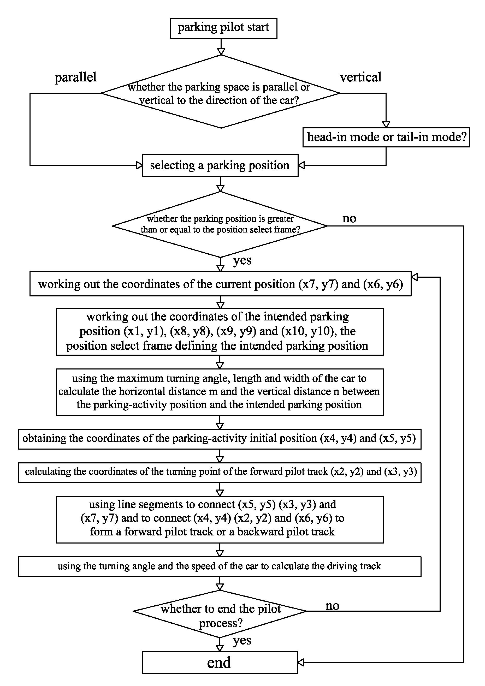
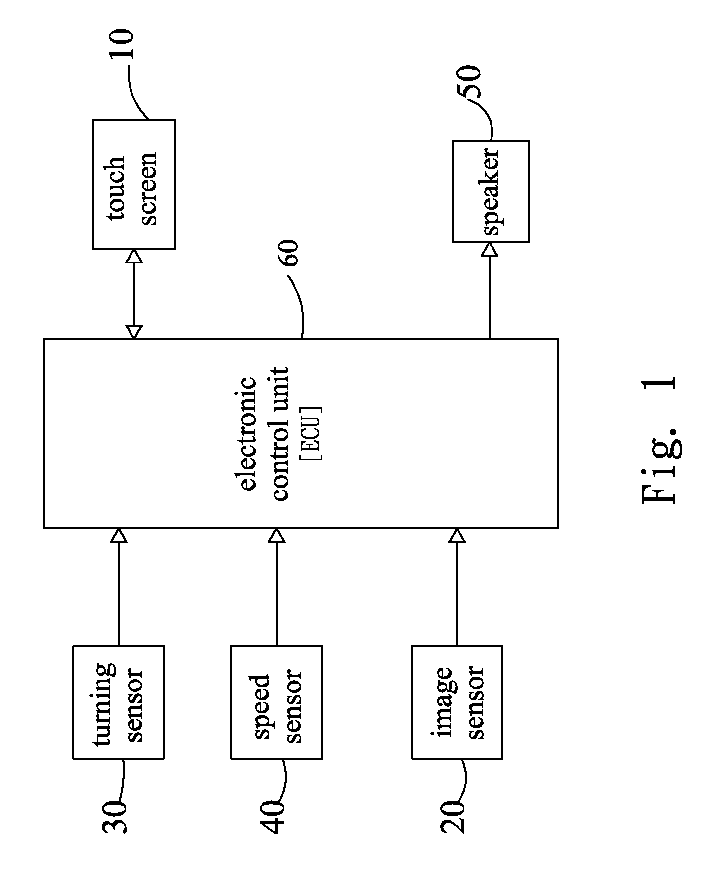
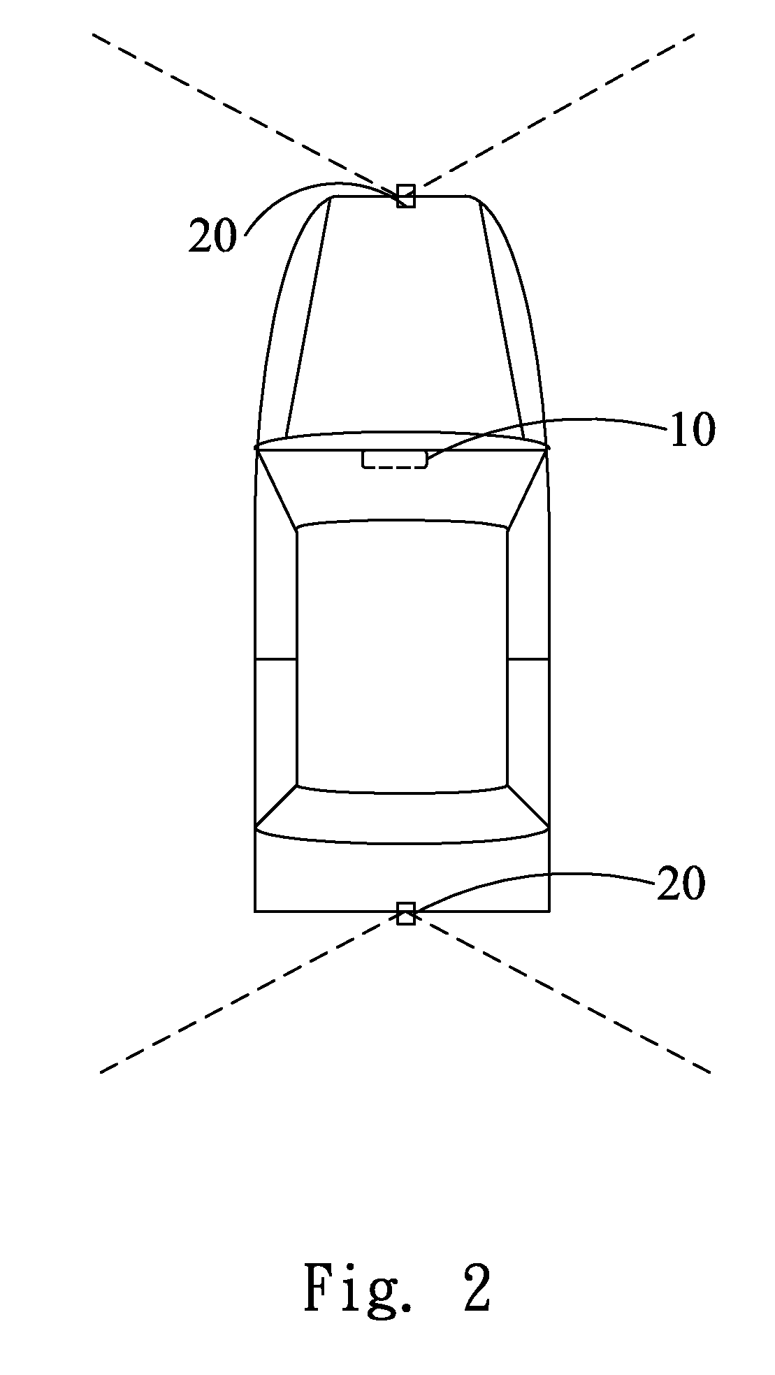
[0012]To achieve the abovementioned objectives, the present invention proposes a parking pilot system and a parking pilot method. The parking pilot system of the present invention comprises a display arranged inside a vehicle and presenting images to a driver; at least one image sensor arranged on the surface the vehicle body and capturing images ahead of the vehicle; at least one speed sensor detecting the speed of the vehicle; and an electronic control unit collecting information and sending out parking instructions. The electronic control unit defines an intended parking position according to the images captured by the image sensor. The electronic control unit calculates the coordinates of the current position and the intended parking position according to the captured images and the detected speed. Then, the electronic control unit works out an initial parking position. According to the adopted parking mode, the electronic control unit presents on the display a forward pilot track extending from the current position through the initial parking position to the intended parking position, or a forward pilot track extending from the current position to the initial parking position. The present invention provides the driver with an available parking track, whereby a driver can easily and efficiently park his vehicle, and whereby an inexperienced or unskillful driver needn't worry about a narrow parking space or a collision with a barrier.

Problems solved by technology

Those laborious and time-consuming parking activities repeat everywhere every day, which are likely to jam traffic or even cause traffic accidents.
Moreover, if the driver is inexperienced or unskillful, the parking process may damage another vehicle or object, which is likely to cause a quarrel.
However, an inexperienced driver is still hard to determine whether the parking area is sufficient to park his vehicle according to the abovementioned information.
Further, limited by the detection range of the distance sensor, an unskillful driver is still hard to park his vehicle into an intended area or even causes a collision with an adjacent barrier.
However, the assistance will not start unless the driver has moved his vehicle to an initial position meeting the requirement of the auxiliary parking system.
Thus, the driver has to move his vehicle to and fro to an initial position, which considerably reduces the value of the auxiliary parking systems.

Method used


Image

  • Parking pilot system and method
  • Parking pilot system and method
  • Parking pilot system and method

Examples


Embodiment Construction

[0038]The present invention proposes a parking pilot system and method, which provides a fast and precise parking pilot process. Firstly, ECU (Electronic Control Unit) uses a position select frame to define an appropriate intended parking position automatically, or the user manually moves the position select frame to an intended parking position on a touchscreen. Based on the intended parking position and the minimum turning radius of a vehicle, the system works out an initial parking position and plans a forward pilot track extending from the current position of the vehicle to the initial parking position. After the vehicle has reached the initial parking position, the system proceeds to plan a parking pilot track extending from the initial parking position to the intended parking position. Then, the system pilots the driver to park the vehicle into the intended parking position smooth and easily. The position select frame will remain on the screen until the vehicle has been parked...


PUM


Abstract

The present invention discloses a parking pilot system and method. The system of the present invention comprises a display, at least one image sensor, at least one speed sensor and an ECU. The ECU uses the images captured by the image sensor to calculate an intended parking position and uses the captured images and the detected speed to work out the coordinates of the current position and the intended parking position. The ECU also works out an initial parking position. According to the adopted parking mode, the ECU presents on the display a forward pilot track extending from the current position through the initial parking position to the intended parking position, or a forward pilot track extending from the current position to the initial parking position. Then, the driver can easily park his vehicle and effectively avoid collision via the pilot instructions presented on the display.

Description

BACKGROUND OF THE INVENTION[0001]1. Field of the Invention[0002]The present invention relates to a parking pilot system, particularly to a parking pilot system and method, which can evaluate the environment and provide the driver with a pilot track to park in an intended position.[0003]2. Description of the Related Art[0004]During traffic-busy hours, a driver usually has to drive around and around to find a parking bay in a heavily crowded area. Sometimes, the driver finds none parking bay eventually. Sometimes, the driver has seen a parking bay, but he passes by and misses it with no chance to return to the parking bay. Sometimes, the driver has found a parking bay, but the inexperienced driver has to move his vehicle to and fro to see whether the parking bay can accommodate his vehicle; if the answer is no, he can only go away to find another parking bay. Those laborious and time-consuming parking activities repeat everywhere every day, which are likely to jam traffic or even caus...

Claims


Application Information

Patent Timeline
Patent Type & Authority Applications(United States)
IPC IPC(8): G06F17/00F26B7/00
CPCG01S5/16B62D15/028
Inventor KUO, YUNG-YUANYU, HSIN-PIN
Owner AUTOMOTIVE RES & TESTING CENT
Learn More