Eureka AIR delivers breakthrough ideas for toughest innovation challenges, trusted by R&D personnel around the world.

Aircraft aero-servo-elasticity ground simulating test system

A technology of servo elasticity and ground simulation, applied in aerodynamic tests, machine/structural component testing, instruments, etc., can solve problems such as difficulty in considering various nonlinear factors, aircraft aerodynamic servo elasticity, and aircraft stability degradation, etc. Achieve the effect of good versatility and scalability, scientific and reasonable principles, and easy comparative research

Active Publication Date: 2010-08-04
BEIHANG UNIV
View PDF2 Cites 33 Cited by
  • Summary
  • Abstract
  • Description
  • Claims
  • Application Information

AI Technical Summary

Problems solved by technology

[0002] Real aircraft have a certain degree of elasticity, and the mutual coupling of the elastic force, inertial force, and unsteady aerodynamic force of the aircraft will cause aeroelasticity problems; the traditional aircraft control and stabilization system is designed to treat the aircraft as a rigid body. This approach ignores the impact of aircraft structural vibration and unsteady aerodynamic forces on the control and stability augmentation system, which may lead to aero-servo-elasticity (ASE) problems of the aircraft, which will reduce the stability of the aircraft and cause instability in severe cases.
At present, there are two main ways to study the problem of aircraft aeroservoelasticity: one is numerical calculation, which requires mathematical modeling of the aircraft as the analysis object and its control and stability augmentation system. This process requires the introduction of many assumptions and it is difficult to consider the real Therefore, the analysis results only have a certain reference value; the other method is wind tunnel test, but the strict requirements of this method on model design and wind tunnel conditions also severely limit its feasibility.

Method used


Image

  • Aircraft aero-servo-elasticity ground simulating test system
  • Aircraft aero-servo-elasticity ground simulating test system
  • Aircraft aero-servo-elasticity ground simulating test system

Examples


Embodiment Construction

[0025] The technical solution of the present invention will be described in detail below in conjunction with the accompanying drawings and specific embodiments.

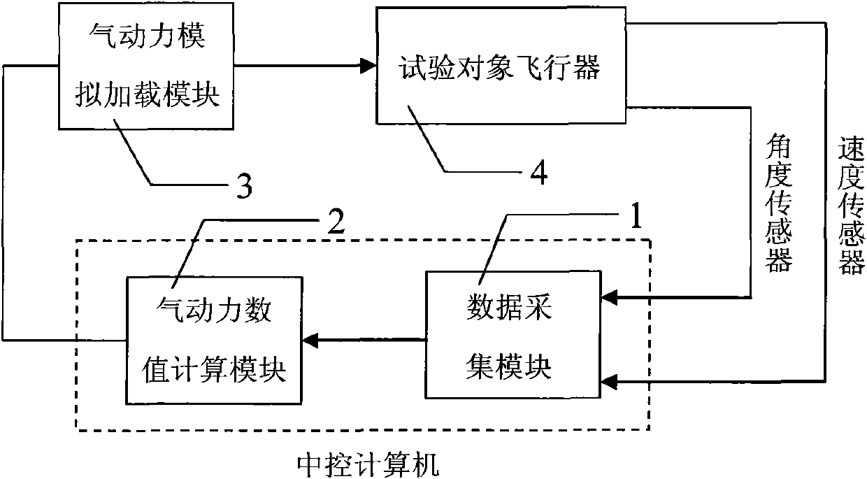
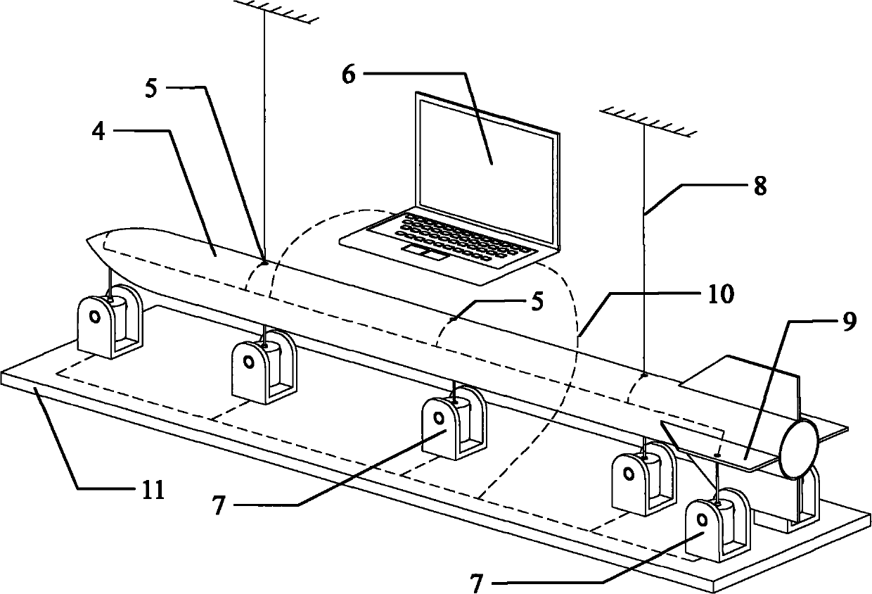
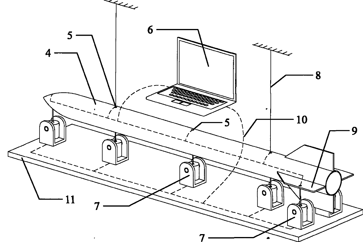
[0026] Such as figure 2 Shown is the hardware arrangement of an embodiment of the present invention, and the test object is such as a slender and slender body missile, and the 4 control rudder surfaces at the tail of the missile body are distributed in a "+" shape, and the rudder surface steering gear is controlled by the flight control stabilization system. drive. Because the projectile body is slender and flexible, the angular rate gyroscope or overload sensor used as the input signal of the missile control and stabilization system not only senses the rigid body motion signal of the missile, but also senses the structural vibration signal of the aircraft, which may cause additional rudder surface vibration. High-frequency vibrations lead to a decrease in the stability of the control and stabilization system origi...


PUM


Abstract

The invention provides an aircraft aero-servo-elasticity (ASE) ground simulating test system which is applied to an aircraft capable of generating the ASE stability loss problem. The whole system comprises a test object aircraft (comprising a control and stability augmentation system), and a motion signal sensor, a central control computer, an aircraft pneumatic force number calculating model, a pneumatic force simulating loading device and the like which are arranged on the aircraft structure. The system carries out real-time measurement and processing on a motion signal of the aircraft, calculates the normal-stationary pneumatic force of the aircraft through a special algorithm on the basis of relevant theory, and realizes the pneumatic force simulating loading through a vibrator. The system is connected with the test aircraft to evaluate the ASE of the aircraft, and can be used for the improvement design of the control and stability augmentation system of the original aircraft and the verification research of the advanced control method.

Description

technical field [0001] The patent of the present invention relates to an aircraft aeroservoelastic ground simulation test system, which can realize the simulated loading of unsteady aerodynamic force of the aircraft, so as to complete the aeroservoelastic ground simulation test of the real aircraft. Background technique [0002] Real aircraft have a certain degree of elasticity, and the mutual coupling of the elastic force, inertial force, and unsteady aerodynamic force of the aircraft will cause aeroelasticity problems; the traditional aircraft control and stabilization system is designed to treat the aircraft as a rigid body. This approach ignores the impact of aircraft structural vibration and unsteady aerodynamic forces on the control and stability augmentation system, which may lead to aero-servo-elasticity (ASE) problems of the aircraft, which will reduce the stability of the aircraft and cause instability in severe cases. . At present, there are two main ways to stud...

Claims


Application Information

Patent Timeline
IPC IPC(8): G01M9/00
Inventor 吴志刚楚龙飞韩鹏杨超
Owner BEIHANG UNIV
Why Eureka
Eureka Blog
Learn More