Heat conversion system

a heat conversion system and heat conversion technology, applied in indirect heat exchangers, heating types, lighting and heating apparatuses, etc., can solve the problems of large electrical energy consumption of blower fans and/or compressors in such equipment, detriment to human life, and high installation and operation costs of back up devices, so as to reduce their electric power and fuel consumption, easy to manufacture, and high efficiency

Inactive Publication Date: 2005-04-28
ROYNAT CAPITAL
View PDF5 Cites 27 Cited by
  • Summary
  • Abstract
  • Description
  • Claims
  • Application Information

AI Technical Summary

Benefits of technology

[0007] It is another object of the present invention to provide an energy conversion system which may be incorporated as an integral component in a heating, cooling, and venting equipment for reducing their electric power and fuel consumption in their normal operation.
[0008] It is another object of the present invention to provide an energy conversion system operating with a

Problems solved by technology

Particularly, the blower fan and/or the compressor in such equipment consume a large amount of electrical energy, since their operating duty cycle between the ON period and the OFF period may be from a few minutes to up to several hours.
In the event of any electric power stoppage or failure which renders such essential equipment ceasing to f

Method used


Image

  • Heat conversion system
  • Heat conversion system
  • Heat conversion system

Examples


Embodiment Construction

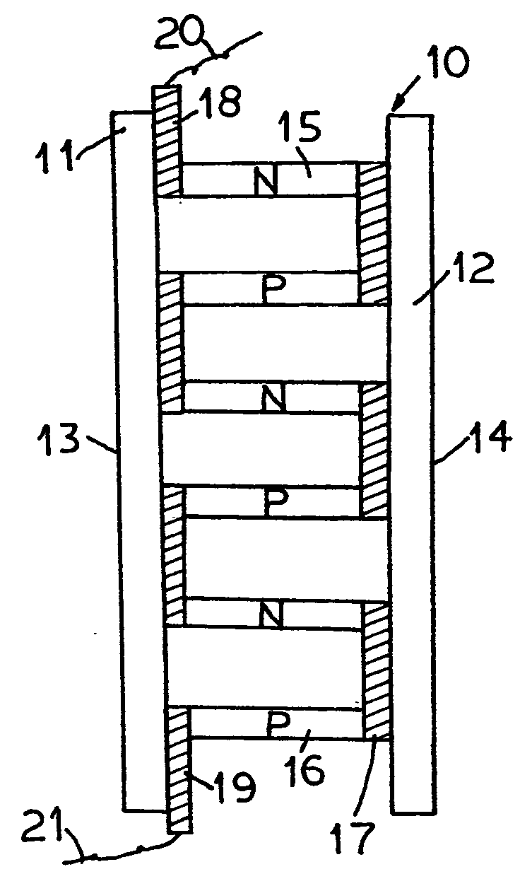
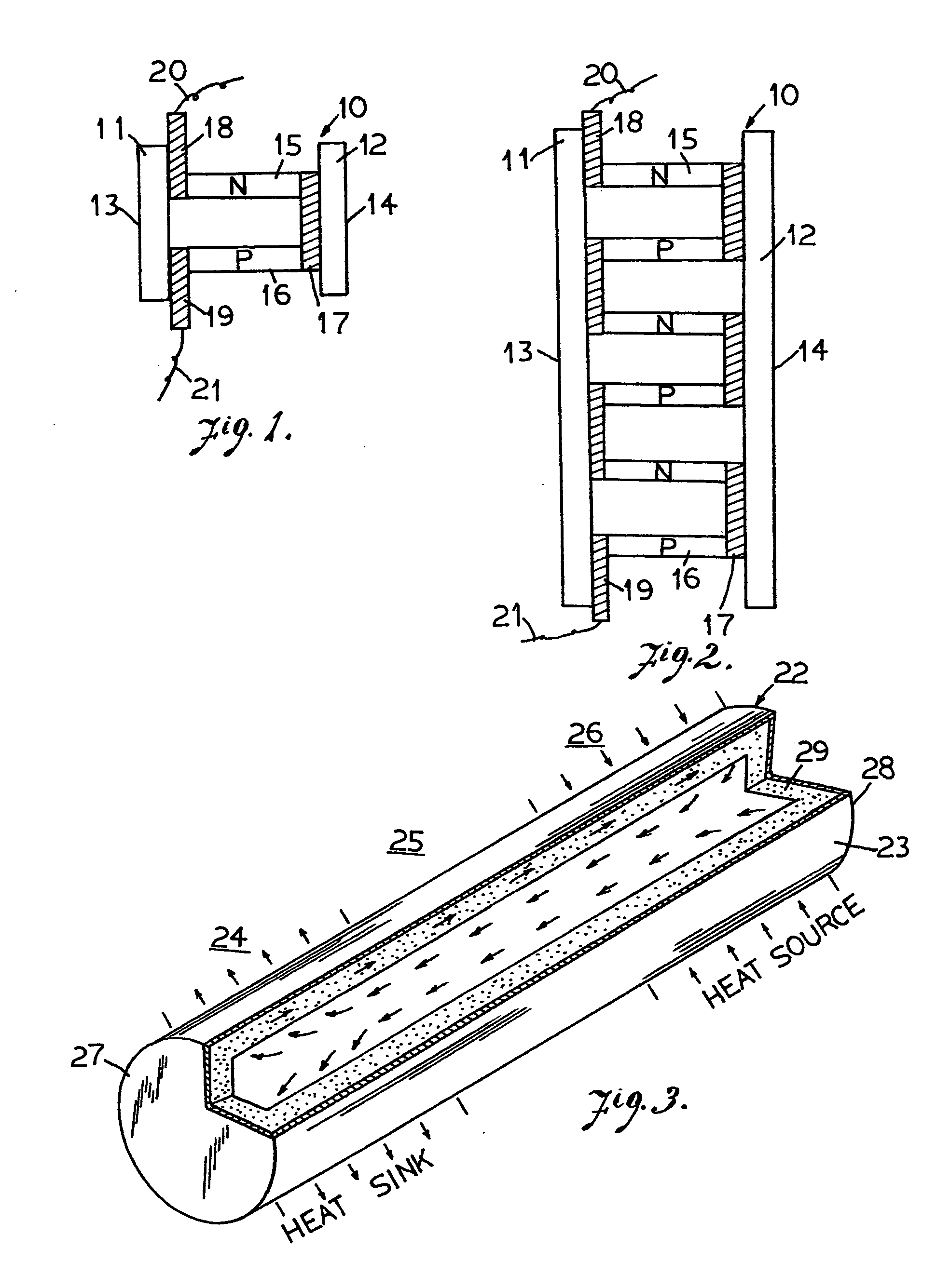
[0024] The conversion system of the present invention employs a thermopile as a basic transducer to derive the electric power required for operating electrical appliances such as the heating, cooling and venting equipment. The operation of the thermopile system may be accomplished by receiving the heat energy provided by an operate-on-demand pilot arrangement. A thermopile consists of a plurality of thermoelectric modules connected together. The construction of a thermoelectric module 10 is best shown in FIG. 1. The thermoelectric module 10 consists of two heat conductive electrical insulator blocks 11 and 12 having outer surfaces 13 and 14 respectively. The external surface 13 of the insulator block 11 is the hot junction of the module, while the external surface 14 of the insulator block 12 is the cold junction. Two spaced parallel different types of semiconductor elements 15 and 16 are located between the insulator blocks 11 and 12. Element 15 is an N-type semiconductor and eleme...


PUM


Abstract

An energy conversion system is provided for converting heat energy from a variety of heat sources to electric power for operating electrical appliances. The system may be incorporated in a power on demand pilot system of a gas operated equipment to provide the sole electric power for operating the equipment. Thermoelectric modules provide the basic transducer for converting the heat energy to electric power and a heat pipe is employed for conducting the heat energy from a heat source to the conversion system.

Description

FIELD OF THE INVENTION [0001] This invention relates to systems for converting heat energy to electric and / or mechanical power. More particularly, it relates to systems for utilizing heat energy from various sources to provide the electric power for operating the electrical components such as the blower fan in a heating, cooling, and venting equipment or other electrical appliances. BACKGROUND OF THE INVENTION [0002] The main components of heating, cooling and venting equipment nowadays all totally dependent on electric power to operate. Particularly, the blower fan and / or the compressor in such equipment consume a large amount of electrical energy, since their operating duty cycle between the ON period and the OFF period may be from a few minutes to up to several hours. Even for an oil or natural gas operated heating furnace, it still requires electrical power to operate and to sustain their electrically operated fuel injector and ignition coil. In cold climate regions, the furnace...

Claims


Application Information

Patent Timeline
IPC IPC(8): F24F5/00H01L35/00H01L35/30
CPCF24F5/0042H01L35/30H01L35/00F28D15/04H10N10/00H10N10/13
Inventor SHAH, REZA H.
Owner ROYNAT CAPITAL
Why Eureka
Try Eureka