Quick-switching valve system, fuel tank system, method for producing a requested mass flow and use of a tank system

A fast switching, fuel tank technology, applied in container discharge methods, fuel cells, fuel cell additives, etc., can solve the problem of unused fluid volume, achieve the effect of improving work reliability and avoiding material displacement

Inactive Publication Date: 2011-11-09
오이겐자이츠아게
View PDF1 Cites 3 Cited by
  • Summary
  • Abstract
  • Description
  • Claims
  • Application Information

AI Technical Summary

Problems solved by technology

Considering the application in the automotive industry, a certain amount of fluid remains unused in the

Method used


Image

  • Quick-switching valve system, fuel tank system, method for producing a requested mass flow and use of a tank system
  • Quick-switching valve system, fuel tank system, method for producing a requested mass flow and use of a tank system
  • Quick-switching valve system, fuel tank system, method for producing a requested mass flow and use of a tank system

Examples


Embodiment Construction

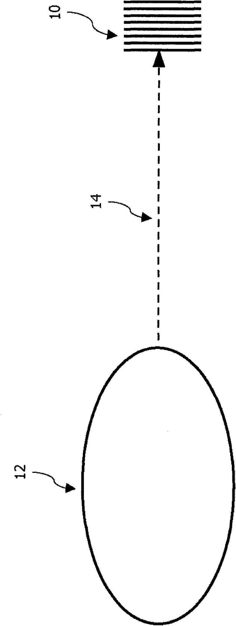
[0066] figure 1 A schematic diagram illustrating the basic principle of supplying the fuel cell 10 with the required mass flow is shown. Hydrogen gas is supplied to a fuel cell 10 of a vehicle (not shown) in this example. In addition, two variable parameters should be taken into account in this principle, namely the input pressure in the fluid accumulator 12 as a function of the hydrogen filling degree of the fluid accumulator 12 and the variability of the mass flow delivered to the fuel cell 10 via the supply line 14 . parameter. The output pressure applied to the outlet of the supply line 14 can be considered as the only constant in this interaction. The output pressure can be, for example, constant at 2.0 bar, whereas the mass flow can range between 0.008 g / sec and 2.500 g / sec as required. For example, only a minimum mass flow is required when the vehicle is idling, whereas a maximum mass flow is required when the vehicle is at maximum power.

[0067] As stated at the o...


PUM


Abstract

The invention relates to an arrangement of pulse-modulated quick-acting valves on a fluid storage device (28', 28''''), wherein the valves (24', 24'''') have different nominal widths for operation thereof in different pressure ranges with otherwise identical structure. The number of the valves (24', 24'''') and the respective nominal widths thereof is selected and matched to a fluctuation range of the pressure in the storage device (28', 28'''') such that over this fluctuation range of the storage device pressure, by complete opening, complete closing and/or switching individual valves or valve combinations, a total dispensed mass flow of the fluid from the storage device (28', 28'''') in a fluctuation range of varying mass flows of constant pressure as required can be produced.

Description

technical field [0001] The invention relates to a system of pulse-modulated fast-switching valves on a fluid accumulator according to claim 1, a fuel tank system with a fluid accumulator according to claim 4, a system according to claim 14 for Method of providing a desired mass flow and use of a fuel tank system according to claim 16. Background technique [0002] Fuel cells are known as energy sources for units in the automotive industry. Fuel cells with proton exchange membranes (Proton Exchange Membrane PEM) are widely used here, in which the anode of the fuel cell is supplied with hydrogen as fuel and the cathode with oxygen as oxidant. Here, the anode and the cathode are separated by a proton exchange membrane, through which protons are exchanged, but the proton exchange membrane cannot conduct electricity. Through an electrochemical reaction, hydrogen and oxygen are converted into water. This produces electrical energy which is harvested via the electrodes at the an...

Claims


Application Information

Patent Timeline
IPC IPC(8): H01M8/04H01M8/06
CPCG05D16/204F17C2223/036F17C2221/012F17C5/06F17C2205/0394F17C13/04F17C2223/0123F17C2265/066F17C2270/0184F17C2270/0168F17C2260/012F17C2201/0109F17C2205/0326F17C2205/0146F17C2205/0142F17C2201/056F17C2205/0382Y02E60/321F17C2260/036F17C2205/0385Y10T137/87917Y02E60/32
Inventor S·格莱泽W·雅尼施
Owner 오이겐자이츠아게
Why Eureka
Try Eureka