
Optical composite film, display panel and display device

A technology for optical composite films and display panels, applied in optics, optical components, nonlinear optics, etc., can solve problems such as low manufacturing cost, defects in optical properties and optical properties, and quality deterioration.

Active Publication Date: 2021-06-18
HKC CORP LTD +1
View PDF0 Cites 0 Cited by
  • Summary
  • Abstract
  • Description
  • Claims
  • Application Information

AI Technical Summary

Problems solved by technology

[0002] The current large-size LCD (Liquid Crystal Display, liquid crystal display) panels include VA (Vertical Alignment, vertical alignment) liquid crystal panels and IPS (In-Plane Switching, in-plane switching) liquid crystal panels, etc. Compared with IPS liquid crystal panels, VA-type liquid crystal panels have more High production efficiency and low manufacturing cost have advantages, but compared with IPS liquid crystal panels, there are obvious optical property defects in optical properties, especially large-size panels require a larger viewing angle for commercial applications, and VA-type liquid crystal panels are used in The brightness of the large viewing angle is rapidly saturated with the voltage, which causes the image quality contrast and color shift of the viewing angle to deteriorate seriously compared with the image quality of the front view, resulting in the problem of color shift
[0003] In addition, the structure of the current LCD display panel is generally a laminated structure, that is, polarizers are attached above and below the liquid crystal layer. However, the thickness of a single layer of the current polarizer is about 200 μm, and the total of the upper and lower layers of polarizers requires 400 μm. thicker

Method used


Image

  • Optical composite film, display panel and display device
  • Optical composite film, display panel and display device
  • Optical composite film, display panel and display device

Examples


Embodiment Construction

[0050] In order to facilitate the understanding of the present invention, the present invention will be described more fully below with reference to the associated drawings. Preferred embodiments of the invention are shown in the accompanying drawings. However, the present invention can be embodied in many different forms and is not limited to the embodiments described herein. On the contrary, these embodiments are provided to make the understanding of the disclosure of the present invention more thorough and comprehensive.

[0051] Unless otherwise defined, all technical and scientific terms used herein have the same meaning as commonly understood by one of ordinary skill in the technical field of the invention. The terminology used herein in the description of the present invention is only for the purpose of describing specific embodiments, and is not intended to limit the present invention.

[0052] Explanation of symbols: ">" means greater than; "<" means less than; "=" ...


PUM

PropertyMeasurementUnit
thicknessaaaaaaaaaa
thicknessaaaaaaaaaa
refractive indexaaaaaaaaaa

Abstract

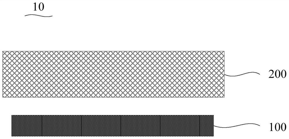
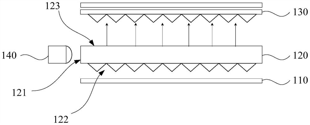
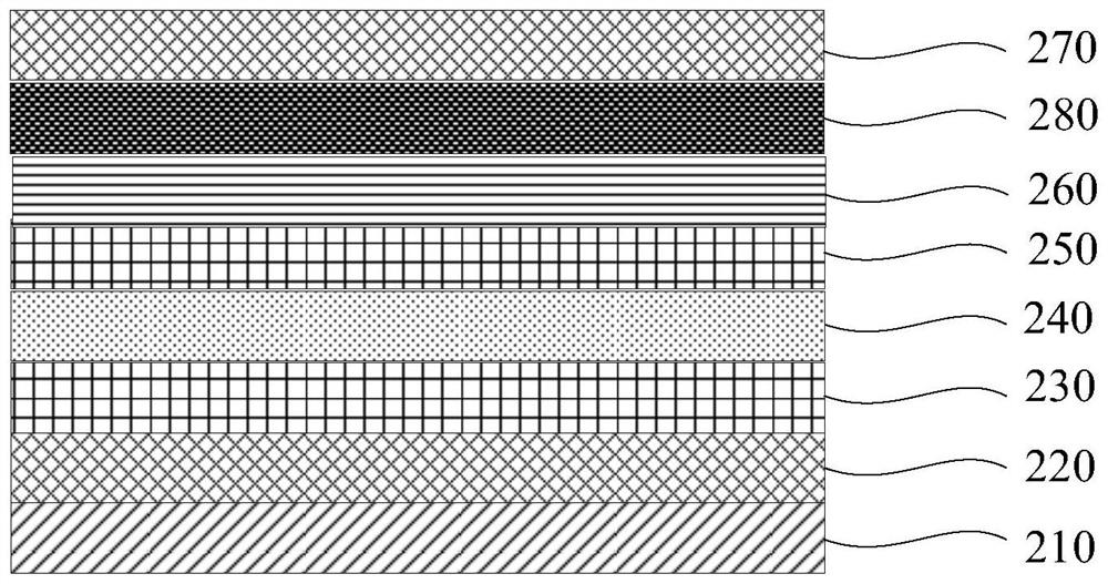
The invention relates to an optical composite film, a display panel and a display device. An optical composite film includes a single optical axis optical film layer, a substrate layer and a reflective grating film layer, the single optical axis optical film layer includes a plate-shaped portion and a plurality of refraction portions formed on one side of the plate-shaped portion, and the multiple refraction portions The part is a curved column or a square prism, and the material of the single-axis optical film layer is a discoid liquid crystal molecule material; the substrate layer is stacked on the side of the plate-shaped part close to the refraction part, and multiple refraction parts are accommodated in the substrate layer. The ordinary light refractive index of the optical axis optical film layer is greater than that of the substrate layer; the reflective grating film layer is arranged on the side of the substrate layer away from the single optical axis optical film layer. The above optical composite film can not only improve the large viewing angle deflection of the display panel, but also make the thickness of the display panel thinner.

Description

technical field [0001] The invention relates to the field of display technology, in particular to an optical composite film, a display panel and a display device. Background technique [0002] The current large-size LCD (Liquid Crystal Display, liquid crystal display) panels include VA (Vertical Alignment, vertical alignment) liquid crystal panels and IPS (In-Plane Switching, in-plane switching) liquid crystal panels, etc. Compared with IPS liquid crystal panels, VA-type liquid crystal panels have more High production efficiency and low manufacturing cost have advantages, but compared with IPS liquid crystal panels, there are obvious optical property defects in optical properties, especially large-size panels require a larger viewing angle for commercial applications, and VA-type liquid crystal panels are used in The brightness of the large viewing angle is rapidly saturated with the voltage, which causes the image quality contrast and color shift of the viewing angle to det...

Claims


Application Information

Patent Timeline
Patent Type & Authority Patents(China)
IPC IPC(8): G02F1/1335G02B5/30
CPCG02F1/133528G02B5/3058G02F1/133548G02F1/13363G02F1/133553
Inventor 康志聪
Owner HKC CORP LTD
Learn More