A small multi-beam planar antenna

A flat-panel antenna, multi-beam technology, applied in the direction of antennas, antenna arrays, antenna combinations with different interactions, etc., can solve the problem of large size of the antenna, and achieve the effect of reducing the area

Active Publication Date: 2019-01-15
CHONGQING JINMEI COMM
View PDF4 Cites 7 Cited by
  • Summary
  • Abstract
  • Description
  • Claims
  • Application Information

AI Technical Summary

Problems solved by technology

After simply superimposing multiple traditional antennas in space, and then using a microwave switch to switch between them, the coverage of the antenna beam can be increased, but the overall size of the antenna in this application mode is relatively large

Method used


Image

  • A small multi-beam planar antenna
  • A small multi-beam planar antenna
  • A small multi-beam planar antenna

Examples


Embodiment Construction

[0014] The present invention will be described in further detail below in conjunction with the accompanying drawings and embodiments.

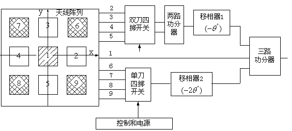
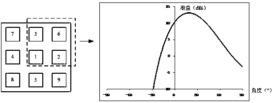
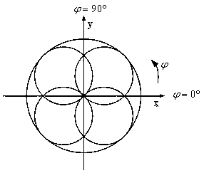
[0015] Such as figure 1 As shown, the present invention proposes a small multi-beam panel antenna, including a planar array and a feed network. The shape of the antenna is flat, the upper layer is a 3×3 planar array composed of nine array elements, the lower layer is the feed network, the feed network includes a single-pole four-throw switch, a double-pole four-throw switch, a two-way power divider, a Three-way power divider, two phase shifters and cables, control board. Using the switch selection and the function of the phase shifter, the four array elements at each corner of the planar array can form a beam that deviates from the normal, and a total of four beams that deviate from the normal can be formed.

[0016] A specific embodiment: the array element spacing is 0.6λ; =75°,2 =150°, f 0 is the center frequency.

[0017] The nine a...


PUM


Abstract

The invention provides a small multi-beam planar antenna which comprises a planar array and a feeding network. The antenna is planar in shape, 3 * 3 planar array composed of 9 array elements in the upper layer, and feed network in the lower layer. The feed network includes SP4T switch, DP4T switch, two-way power splitter, three-way power splitter, phase shifter, cable and control board. With the action of switch selection and phase shifter, four array elements in each corner of the planar array can form a beam which deviates from the normal line, and four beams which deviate from the normal line can be formed altogether. The combination of the four narrow beams achieves wide angular coverage and the antenna area is reduced by 44% due to element multiplexing.

Description

technical field [0001] The invention relates to a multi-beam antenna technology, in particular to a beam switching antenna. Background technique [0002] High-gain directional antennas are limited in application due to the inherent characteristics of narrow beams. On the one hand, the narrow beam makes the coverage of the wireless network smaller, and the coverage of a larger area requires multi-faceted antennas, which makes the system complex. On the other hand, the narrow beam makes it more difficult for the antenna to aim at the predetermined area, especially when the directional antenna is located on the moving platform; although the servo tracking system can solve this problem, the servo system is bulky, expensive, and tracking control is complicated. [0003] The beam switching antenna is a simple implementation of the multi-beam antenna, which uses a microwave switch to switch multiple inherent beams. After simply superimposing multiple traditional antennas in space...

Claims


Application Information

Patent Timeline
Patent Type & Authority Applications(China)
IPC IPC(8): H01Q21/29H01Q21/00
CPCH01Q21/0006H01Q21/29
Inventor 魏瑰周继华王将宏刘航赵涛唐先建钟志强殷志宏王翰墨杨鹏廖西斌刘中全胡丹耀徐德涛王韬
Owner CHONGQING JINMEI COMM
Why Eureka
Try Eureka