Fruit collector
A harvester and fruit technology, applied in picking machines, agricultural machinery and implements, applications, etc., can solve the problems of fruit damage, low efficiency, low work efficiency, time-consuming and labor-intensive problems, and achieve convenient insertion and removal Effect
- Summary
- Abstract
- Description
- Claims
- Application Information
AI Technical Summary
Problems solved by technology
Method used
Image

Examples
Embodiment 1
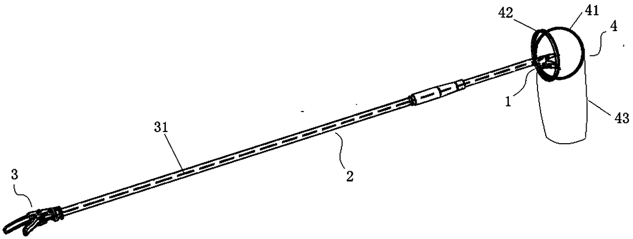
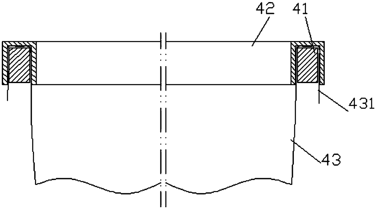
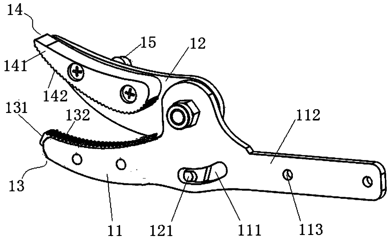
[0029] Such as figure 1 , the fruit picker of the present invention comprises picking unit 1, picking control unit 3, collecting unit 4 and bar 2, and picking unit 3 and collecting unit 4 are located at the upper end of bar 2 (the upper and lower ends of bar are pressed when working) The use state is determined), the picking control unit 3 is arranged at the lower end of the rod 2. The collection unit 4 includes a fixed ring 41 , an insertion ring 42 and a collection bag 43 , and the fixed ring 41 is located under the picking list 1 . Such as figure 2 , the opening end 431 of the collection bag 43 is wound on the fixed ring, and the insert ring 42 is plugged and wound on the fixed ring wound around the open end 431 of the collection bag 43, so that the collection bag is fixed on the fixed ring. Such as image 3 , the picking unit 1 includes a first cut piece 11 and a second cut piece 12 , the two cut pieces are hinged and form a cross cut 10 . Such as Figure 4 , the pic...
Embodiment 2
[0038] Such as Figure 11 , the first clamping body 13 and the second clamping body 14 in the present embodiment are respectively connected on the outer surface of the first shearing piece 11 and the inner surface of the second shearing piece 12, and the thickness of the second clamping body 14 is the same as The thickness of the superposition of the first clamping body 13 and the first shear piece 11 is equivalent, and the first fixing nail 15 is arranged on the first clamping body 13, and one end of the flexible steel wire shaft 33 is connected on the fixing nail 15, and the other end passes through the fixing nail 15. The rod is connected to the second fixing nail 36 of the rotating handle by going around the locking plate 35 . When carrying out the picking operation, the finger pulls the turning handle 32 to pull the flexible steel wire shaft 33 to make the first cutting piece 11 rotate relative to the second cutting piece 12 .
[0039] Other structures and working princi...
Embodiment 3
[0041] Such as Figure 12 , the first clamping body 13 and the second clamping body 14 in the present embodiment are respectively connected on the inner sides of the first clipping piece 11 and the second clipping piece 12, and the thickness of the first clipping body 13 is the same as that of the second clipping body. The thickness of the holding body 14 is equivalent, and the first fixing nail 15 is arranged on the outer surface of the first shearing piece 11 . And, the rod 2 in the present embodiment is a bamboo pole, the flexible steel wire shaft cannot pass through the rod, and the flexible steel wire 31 is guided from the outside of the rod to the picking control unit 3 at the lower end of the rod, as Figure 10 1. One end of the flexible steel wire shaft 31 is connected to the second fixing nail 36 of the rotating handle around the locking plate 35 . When carrying out the picking operation, the finger pulls the turning handle 32 to pull the flexible steel wire shaft 33...
PUM
 Abstract
Description
Claims
Application Information