Assembly chain cutter

A truncation device and chain technology, which is applied to metal chains, tools for repairing chains by metal processing, manufacturing tools, etc., can solve the problems of positional deviation of truncation, hand knock injury, movement, etc., so as to achieve convenient truncation and prevent smashing injuries. Effect

Active Publication Date: 2019-01-18
杭州东腾实业有限公司
View PDF6 Cites 8 Cited by
  • Summary
  • Abstract
  • Description
  • Claims
  • Application Information

AI Technical Summary

Problems solved by technology

[0002] When assembling mechanical products, chains are always used, but when the chain is too long, the chain needs to be cut to the required length before assembly. Usually, people use a hammer to cut the chain with a bolt in hand, and it is easy to knock their own hands.

Method used


Image

  • Assembly chain cutter
  • Assembly chain cutter

Examples


Embodiment 1

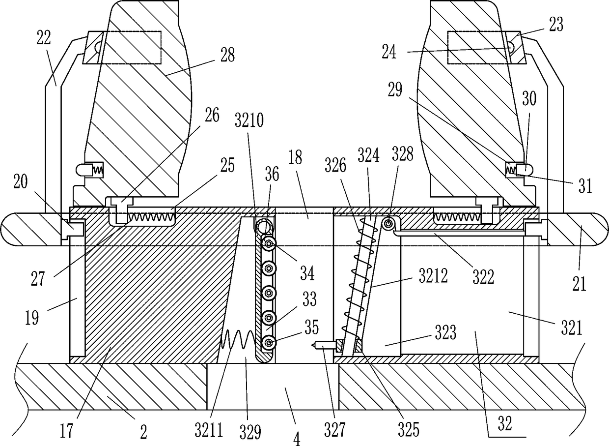
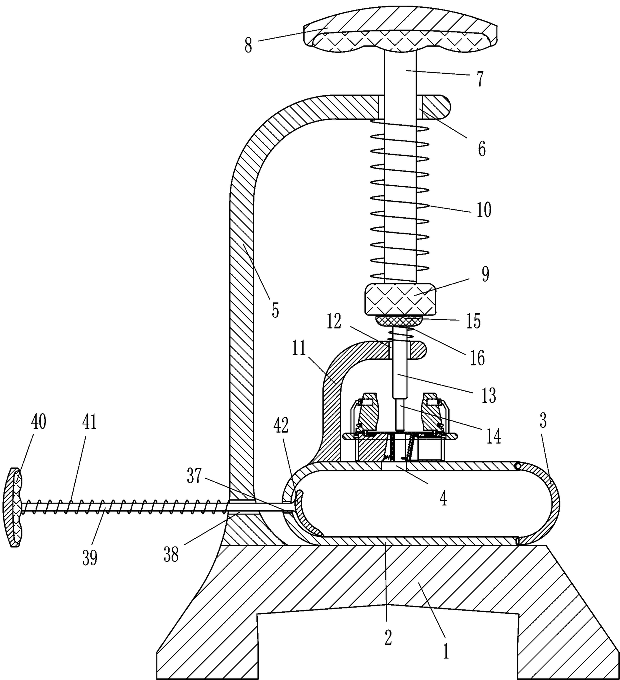
[0018] A chain cutter for assembly, such as Figure 1-2As shown, it includes a base 1, a box body 2, a cover plate 3, a first 7-shaped plate 5, a movable rod 7, a pull plate 8, a knocking block 9, a first spring 10, a second 7-shaped plate 11, and a guide rod 13 , latch 14, contact block 15, second spring 16, fixed block 17, vertical slider 20, annular plate 21, support rod 22, u-shaped sleeve 23, horizontal slider 26, third spring 27, pressure block 28, The block 30 and the fourth spring 31, the top right side of the base 1 is fixedly connected with the box body 2, the upper right side of the box body 2 is connected with the cover plate 3 in a rotatable manner, the cover plate 3 cooperates with the box body 2, and the top left side of the box body 2 There is a feed port 4 on the side, and a fixed block 17 is fixed on the left side of the outer top of the box body 2. The middle part of the fixed block 17 has a through hole 18. The through hole 18 is located directly above the ...

Embodiment 2

[0020] A chain cutter for assembly, such as Figure 1-2 As shown, it includes a base 1, a box body 2, a cover plate 3, a first 7-shaped plate 5, a movable rod 7, a pull plate 8, a knocking block 9, a first spring 10, a second 7-shaped plate 11, and a guide rod 13 , latch 14, contact block 15, second spring 16, fixed block 17, vertical slider 20, annular plate 21, support rod 22, u-shaped sleeve 23, horizontal slider 26, third spring 27, pressure block 28, The block 30 and the fourth spring 31, the top right side of the base 1 is fixedly connected with the box body 2, the upper right side of the box body 2 is connected with the cover plate 3 in a rotatable manner, the cover plate 3 cooperates with the box body 2, and the top left side of the box body 2 There is a feed port 4 on the side, and a fixed block 17 is fixed on the left side of the outer top of the box body 2. The middle part of the fixed block 17 has a through hole 18. The through hole 18 is located directly above the...

Embodiment 3

[0023] A chain cutter for assembly, such as Figure 1-2 As shown, it includes a base 1, a box body 2, a cover plate 3, a first 7-shaped plate 5, a movable rod 7, a pull plate 8, a knocking block 9, a first spring 10, a second 7-shaped plate 11, and a guide rod 13 , latch 14, contact block 15, second spring 16, fixed block 17, vertical slider 20, annular plate 21, support rod 22, u-shaped sleeve 23, horizontal slider 26, third spring 27, pressure block 28, The block 30 and the fourth spring 31, the top right side of the base 1 is fixedly connected with the box body 2, the upper right side of the box body 2 is connected with the cover plate 3 in a rotatable manner, the cover plate 3 cooperates with the box body 2, and the top left side of the box body 2 There is a feed port 4 on the side, and a fixed block 17 is fixed on the left side of the outer top of the box body 2. The middle part of the fixed block 17 has a through hole 18. The through hole 18 is located directly above the...


PUM


Abstract

The invention relates to a cutter, in particular to an assembly chain cutter. The assembly chain cutter aims at achieving the technical purposes that a chain can be fixed to be cut off so that the hands can be prevented from being injured, and the cut-off portion is accurate. The assembly chain cutter comprises a base, a box body, a cover plate, a first inverted-L-shaped plate, a movable rod, a pull plate, a tapping block, a first spring, a second inverted-L-shaped plate, a guide rod, a bolt, a contact block and the like; the right side of the top of the base is fixedly connected with the boxbody, the cover plate is rotatably connected to the upper portion of the right side of the box body and cooperates with the box body, a feeding port is formed in the left side of the top of the box body, and a fixing block is fixedly connected to the left side of the outer top of the box body. According to the assembly chain cutter, under the function of a pressing block, the chain can be fixed, and therefore the situation can be avoided that the chain moves and the cut-off portion deviates; by pulling the pull plate, the bolt can cut off the chain, an operator more conveniently cuts off the chain, and the hands can also be prevented from being injured by a crashing object.

Description

technical field [0001] The invention relates to a cutter, in particular to a chain cutter for assembly. Background technique [0002] When assembling mechanical products, chains are always used, but when the chain is too long, the chain needs to be cut to the required length before assembly. Usually, people use a hammer to cut the chain with a bolt in hand, and it is easy to knock their own hands. Injury, and because the chain is not fixed, it is easy to move and cause the truncation position to deviate, so people will wear thick gloves to cut the chain, and fix the chain with a fixed device. Such thick gloves allow the operator to cut the chain more inconvenient. Contents of the invention [0003] In order to overcome the disadvantages that people usually cut off the chain with a hammer and hit it with a bolt in their hands, it is easy to knock their own hands, and because the chain is not fixed, it is easy to move and cause deviations in the cut-off position. The techni...

Claims


Application Information

Patent Timeline
IPC IPC(8): B21L21/00
CPCB21L21/00
Inventor 邱国盛
Owner 杭州东腾实业有限公司
Why Eureka
Try Eureka