Novel high-slope displacement and settlement monitoring device and use method thereof

A settlement monitoring and slope technology, applied in measuring devices, height/level measurement, excavation, etc., can solve the problem that the pile body cannot reach the corresponding position according to the specification requirements, the displacement pile is difficult to dig holes manually, and the deviation of the measurement result is too large, etc. problems, to achieve the effects of reducing impact, facilitating disassembly, and reducing disturbance

Pending Publication Date: 2019-01-18
CHANGAN UNIV
View PDF0 Cites 0 Cited by
  • Summary
  • Abstract
  • Description
  • Claims
  • Application Information

AI Technical Summary

Problems solved by technology

[0003] Currently, the monitoring devices placed on the surface of high slope platforms are mainly cast-in-situ concrete piles. However, during the construction of high slopes, it is easy to artificially damage the piles, resulting in excessive deviation of measurement results or difficulty in measurement; secondly, for geological For high slopes with poor conditions, it is difficult to manually dig holes when burying displacement piles, resulting in the piles not reaching the corresponding positions according to the specification requirements; moreover, after the monitoring is completed, the displacement piles on the high slope platform cannot be recycled and reused , resulting in a waste of resources

Method used


Image

  • Novel high-slope displacement and settlement monitoring device and use method thereof
  • Novel high-slope displacement and settlement monitoring device and use method thereof
  • Novel high-slope displacement and settlement monitoring device and use method thereof

Examples


Embodiment Construction

[0039] The present invention will be further introduced below in conjunction with the accompanying drawings.

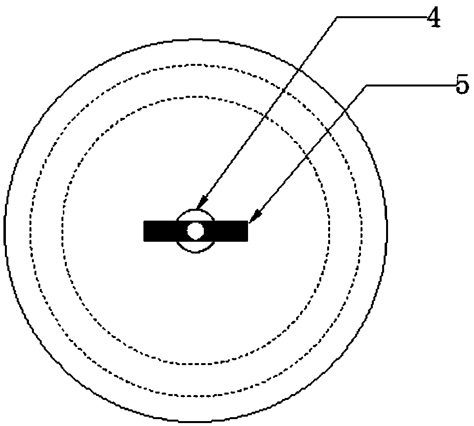
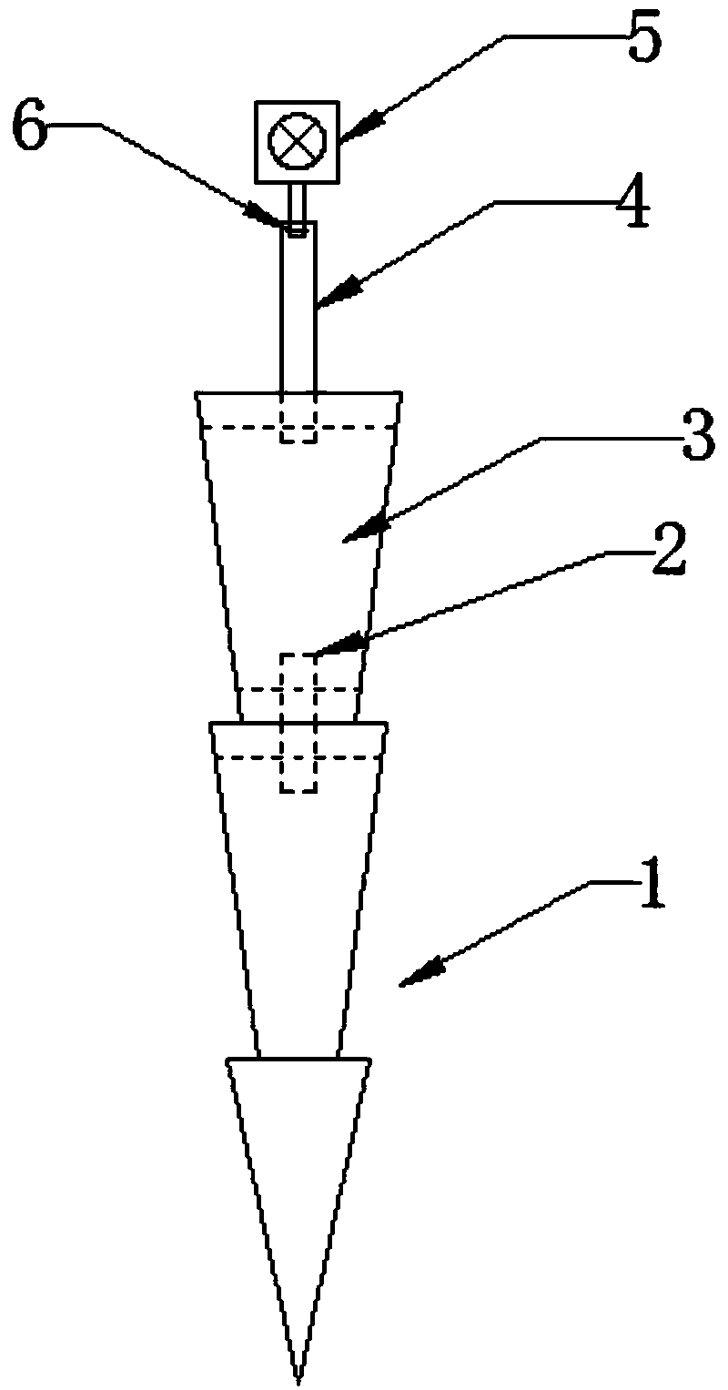
[0040] figure 1 Shown is a three-dimensional schematic diagram of a novel high slope surface displacement and settlement monitoring device of the present invention, which includes a lower column 1 and an upper column 3, and a stud bolt 2 is used to connect the upper column 3 and the lower column 1 , the upper column 3 and the lower column 1 are connected by stud bolts 2, which avoids the inconvenience caused by the use of integral concrete cast-in-place piles in the past, makes the installation of the device faster and more stable, and greatly saves time and labor of personnel; the upper column The body 3 adopts a variable section setting, and its cross-sectional area gradually decreases from top to bottom. Bolt holes are provided on the top surface of the upper column body 3, that is, the top bolt hole 32 of the upper column body. The bolt hole 32 at the top of the u...


PUM

PropertyMeasurementUnit
Heightaaaaaaaaaa

Abstract

The invention relates to a novel high-slope displacement and settlement monitoring device and a use method thereof. The device includes an upper cylinder body and a lower cylinder body disposed by using variable cross-sections. The lower cylinder body also includes a cone body located at a lower portion. The lower cylinder body disposed in a cone manner is simpler in installing, and placing of thelower cylinder body to a position required by specification is easily realized. At the same time, the lower cylinder body is disposed by using a variable cross-section, the variable cross-section isinside a soil body, and the lower cylinder body is more stable through close contact with the soil body. The lower cylinder body and the upper cylinder body are connected by using a stud bolt. A single-head bolt is connected with a top surface of the upper cylinder body in a thread manner. A hole slot is disposed on the top of the single-head bolt and is used for installing a prism. Therefore, adjustment on prism height can be realized simply through rotating the single-head bolt. According to the device, detachability among various components is realized through the stud bolt and the single-head bolt; and on the one hand, adjustment on the height is facilitated, and on the other hand, recycling can be carried out after use is completed, a structure is simple, and use is convenient.

Description

technical field [0001] The invention belongs to the field of high slope engineering construction, and in particular relates to a novel high slope displacement and settlement monitoring device and an application method thereof. Background technique [0002] With the continuous development of national infrastructure and the continuous improvement of road and railway traffic network planning, attention must be paid to the safety of high slope construction. Due to the particularity and complexity of the geological conditions of high slope engineering construction, monitoring and measuring the surface displacement and settlement of the high slope platform is an indispensable means to ensure the normal construction of the high slope and the safe operation in the later stage. Among them, the surface displacement and settlement of all levels of high slope platforms is one of the must-measure items in the monitoring and measurement of high slopes. Feedback the data to the constructi...

Claims


Application Information

Patent Timeline
IPC IPC(8): G01C5/00G01B21/02E02D17/20
CPCG01B21/02G01C5/00E02D17/20
Inventor 王志丰郭昊天陈龙龙陈富翔王亚琼
Owner CHANGAN UNIV
Why Eureka
Try Eureka