
Automatic oriented transformer substation partial discharge monitoring positioning device and method

A technology for orientation devices and substations, which is applied in the direction of using optical methods for testing and testing dielectric strength, etc., which can solve the problems of increasing costs, inconvenient operation, and consumption, and achieve high-precision orientation, time-saving, and accurate positioning.

Pending Publication Date: 2019-01-18
HONGHE POWER SUPPLY BUREAU OF YUNNAN POWER GRID
View PDF0 Cites 1 Cited by
  • Summary
  • Abstract
  • Description
  • Claims
  • Application Information

AI Technical Summary

Problems solved by technology

[0004] However, the existing partial discharge detection and positioning equipment is basically aimed at a single substation equipment (transformer, capacitive equipment, GIS, etc.) The signal and the electric signal can be positioned together, which makes the existing methods have some defects
The equipment in the substation has the possibility of partial discharge. If you want to monitor the electrical equipment in the whole station in real time and simply rely on one-to-one detection equipment, you need to install a partial discharge detection device on each equipment. A lot of human, material and financial resources
And it is very inconvenient to operate, and it is also not conducive to post-maintenance work such as overhaul
Especially in substations of 220kV and above, due to the large number of electrical primary and secondary equipment, if this method is used for partial discharge detection, unnecessary costs will be greatly increased
This form of detection will also be very difficult to adapt to the development trend of "unmanned smart substation" in the future

Method used


Image

  • Automatic oriented transformer substation partial discharge monitoring positioning device and method
  • Automatic oriented transformer substation partial discharge monitoring positioning device and method
  • Automatic oriented transformer substation partial discharge monitoring positioning device and method

Examples


Embodiment Construction

[0062] The preferred embodiments of the present invention will be described in detail below with reference to the accompanying drawings.

[0063] 1 Automatic orientation device for substation partial discharge monitoring

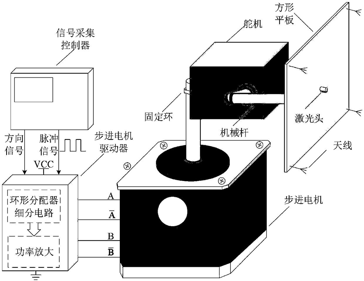
[0064] From the analysis of existing technologies and products, it can be seen that the existing substation partial discharge monitoring devices can only monitor one power equipment, and the required devices and manpower are relatively large. In order to realize the partial discharge monitoring of the whole substation in multiple directions, and intuitively indicate the actual location of the defect so as to facilitate the follow-up maintenance work, the present invention proposes an automatic orientation device for partial discharge monitoring of the substation. Its structure is as follows figure 1 shown.

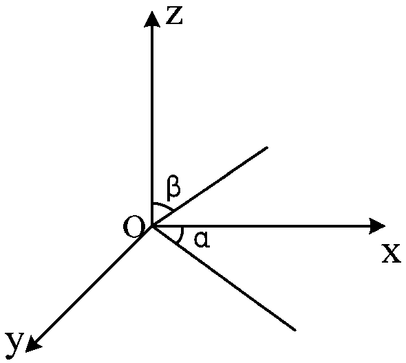
[0065] figure 1 Among them, the main structure includes an antenna array composed of four omnidirectional antennas, a square plate on which the antenn...


PUM

PropertyMeasurementUnit
Sampling rateaaaaaaaaaa

Abstract

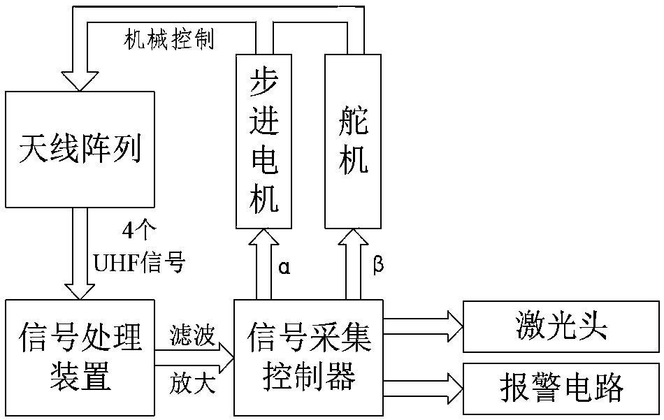
The invention relates to an automatic oriented transformer substation partial discharge monitoring positioning device and method, and belongs to the field of the power monitoring. The device comprisesan automatic orientation device, a signal collection controller, a signal processing device and an alarm circuit; the signal collection controller is used as a central processing unit to analyze an amplified and filtered abnormal signal; the signal is repeatedly sampled, analyzed, computed, transmitted, and controlled until the UHF signal time difference is within the preset threshold; the signalprocessor controls a laser head of the automatic orientation device to start, and enables the laser head to point to the partial discharge location, thereby realizing multi-directional partial discharge monitoring of an antenna array. The invention provides an automatic orientation device of partial discharge monitoring; the automatic orientation device can adjust the antenna array orientation inmulti-angle, the device can realize the function of monitoring equipment at multiple directions without installing monitoring equipment on each device needing the partial discharge monitoring; the overhauling efficiency is improved, thereby ensuring that the antenna array can rotate to any direction in a three-dimensional direction.

Description

technical field [0001] The invention belongs to the field of electric power monitoring, and relates to an automatic directional substation partial discharge monitoring and positioning device and method. Background technique [0002] Insulation fault is one of the main faults in the operation of power equipment. Before the insulation fault of power equipment occurs, there will generally be a gradual partial discharge process, which will eventually lead to insulation breakdown. If partial discharge monitoring and diagnosis of operating equipment can be carried out during this process, partial discharge signals can be detected in time, and defects can be dealt with in advance, so that the occurrence of insulation breakdown faults can be effectively avoided. At present, the partial discharge detection and positioning of substation equipment are mainly carried out for specific single equipment such as GIS, transformers, and capacitive equipment. Using this method to implement p...

Claims


Application Information

Patent Timeline
IPC IPC(8): G01R31/12
CPCG01R31/1218
Inventor 李杰李家保王应芬肖佳杨志华李时珍续所良马学林余骁王榭崟徐芸
Owner HONGHE POWER SUPPLY BUREAU OF YUNNAN POWER GRID
Learn More