Heat dissipation distribution cabinet

A distribution box and box body technology, applied in electrical components, substation/switch layout details, substation/switchgear cooling/ventilation, etc., can solve the problem of poor heat dissipation of the distribution box, poor light inside the distribution box, etc. problems, to achieve the effect of stable resistance, convenient installation, and reduced failure rate

Inactive Publication Date: 2019-01-18
常州耀洲众创空间有限公司
View PDF3 Cites 4 Cited by
  • Summary
  • Abstract
  • Description
  • Claims
  • Application Information

AI Technical Summary

Problems solved by technology

[0005] In order to overcome the problems of poor internal light and poor heat dissipation in the distribution box in the prior art, the present invention provides a heat dissipation distribution box

Method used


Image

  • Heat dissipation distribution cabinet
  • Heat dissipation distribution cabinet
  • Heat dissipation distribution cabinet

Examples


Embodiment 1

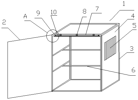
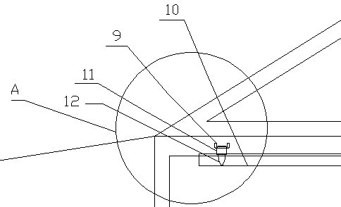
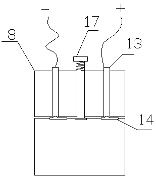
[0036] Such as figure 1 As shown, a heat dissipation distribution box includes a box body 1 and a box door 2. The box body 1 is composed of a frame 3 and a box plate 4. The box door 2 and the box body 1 are connected by a rotating shaft type living hinge; the side of the box body 1 There are vents 5; the box body 1 also has reinforcing ribs 6 inside, and the reinforcing ribs 6 are located in the middle of the frame 3 and are fixedly connected with the frame 3; The joint 8 has a power supply interface inside the fixed joint 8 , the beam 7 is provided with hooks 9 at least on both sides, and the fixed joint is connected with a lighting mechanism 10 . Such as figure 2 As shown, the lighting mechanism 10 is in the shape of a strip, and the lighting mechanism 10 has a buckle 11 at a position corresponding to the hook of the crossbeam 7, and the hook 11 has a tensioning handle 12 thereon.

[0037] Such as Figure 11 As shown, the air vent 5 is composed of a heat-conducting main ...

Embodiment 2

[0046] refer to figure 1 As shown, a heat dissipation distribution box includes a box body 1 and a box door 2. The box body 1 is composed of a frame 3 and a box plate 4. The box door 2 and the box body 1 are connected by a rotating shaft type living hinge; the side of the box body 1 There are vents 5; the box body 1 also has reinforcing ribs 6 inside, and the reinforcing ribs 6 are located in the middle of the frame 3 and are fixedly connected with the frame 3; The joint 8 has a power supply interface inside the fixed joint 8 , the beam 7 is provided with hooks 9 at least on both sides, and the fixed joint is connected with a lighting mechanism 10 . Such as figure 2 As shown, the lighting mechanism 10 is in the shape of a strip, and the lighting mechanism 10 has a buckle 11 at a position corresponding to the hook of the crossbeam 7, and the hook 11 has a tensioning handle 12 thereon. refer to Figure 11 As shown, the air vent 5 is composed of a heat-conducting main copper ...

Embodiment 3

[0049] refer to figure 1 As shown, a heat dissipation distribution box includes a box body 1 and a box door 2. The box body 1 is composed of a frame 3 and a box plate 4. The box door 2 and the box body 1 are connected by a rotating shaft type living hinge; the side of the box body 1 There are vents 5; the box body 1 also has reinforcing ribs 6 inside, and the reinforcing ribs 6 are located in the middle of the frame 3 and are fixedly connected with the frame 3; The joint 8 has a power supply interface inside the fixed joint 8 , the beam 7 is provided with hooks 9 at least on both sides, and the fixed joint is connected with a lighting mechanism 10 . The structures and functions of other components are the same as in Embodiment 1. The difference with embodiment 1 is: as Figure 7 As shown, there are 6 copper tubes 13, which are arranged equidistantly along the circumferential direction, and the angle between every two adjacent copper tubes is 60 degrees; each pair of the two ...


PUM


Abstract

The invention provides a heat dissipation distribution cabinet, comprising a box body and a box door. The box body is composed of a frame and a box plate. The box door and the box body are connected with each other through a rotary shaft type movable hinge. The inside of the box body is also provided with reinforcing ribs, which are arranged in the middle of the frame and are fixedly connected with the frame; the side of the box body is provided with an air vent; The top end of the box body close to the box door is provided with a fixed joint along the longitudinal direction of the cross beam,the fixed joint is provided with a power supply interface, the cross beam is provided with hooks on at least two sides, and the fixed joint is connected with a lighting mechanism. The heat dissipation distribution box provided by the invention can illuminate the interior of the distribution box, is convenient for maintenance personnel to inspect and repair, and the opening of the door of the distribution box is fully automated, does not require personnel operation, and is intelligent and convenient. The distribution box also has a heat dissipation function, which can absorb the heat in the box, thereby protecting the safety of the electrical accessories in the distribution box.

Description

technical field [0001] The invention relates to the technical field of electrical equipment, in particular to a heat dissipation distribution box. Background technique [0002] The distribution box is a kind of electrical equipment, which is the power distribution equipment used for power distribution, control, metering and cable connection in the power supply system, and is the general control center of various electrical appliances. The outside line first enters the main control switch in the cabinet, and then enters the sub-control switch, and each branch is set according to its needs. Such as instrumentation, automatic control, motor magnetic switch, various AC contactors, etc. Some also have high-voltage room and low-voltage room switch cabinets, and high-voltage busbars, such as power plants. In the prior art, as more and more electrical components and wires and cables need to be accommodated inside the distribution box, the volume of the distribution box also becomes...

Claims


Application Information

Patent Timeline
Patent Type & Authority Applications(China)
IPC IPC(8): H02B1/46H02B1/56
CPCH02B1/46H02B1/565
Inventor 王兰云
Owner 常州耀洲众创空间有限公司
Why Eureka
Try Eureka