Multi-stage ejecting speed-increasing dust-collecting device

A collection port and wind flow technology, which is applied in the swirl device, the device whose axial direction can be reversed, etc., can solve the problems of slow sedimentation collection speed, high dust content in the air outlet, and small processing air volume, so as to improve Dust removal efficiency and dust removal effect, improvement of dust removal effect, and accelerated discharge effect

Inactive Publication Date: 2019-01-22
ANHUI UNIV OF SCI & TECH
View PDF0 Cites 0 Cited by
  • Summary
  • Abstract
  • Description
  • Claims
  • Application Information

AI Technical Summary

Benefits of technology

This new design improves cleanliness by removing particles from materials more effectively without causing them to get stuck or damaged during subsequent processing steps. It uses multiple stages for efficient separation of small solid objects that are difficult to remove evenly distributed throughout large volumes of space while maintaining consistently high levels of purity.

Problems solved by technology

This patented technical problem addressed by this patents relates to improving the efficiency or effectiveness of cyclones used for removing particulate matter (PM) emissions from industrial processes such as combustion engines. Cyclone separators have limitations due to their design which results in partial particle capture without complete cleaning and excessive accumulation on certain parts inside them.

Method used


Image

  • Multi-stage ejecting speed-increasing dust-collecting device
  • Multi-stage ejecting speed-increasing dust-collecting device
  • Multi-stage ejecting speed-increasing dust-collecting device

Examples


Embodiment Construction

[0015] Attached below Figure 1-3 and specific embodiments to further describe the present invention, and the schematic embodiments and descriptions of the present invention are used to explain the present invention, but not as a limitation to the present invention.

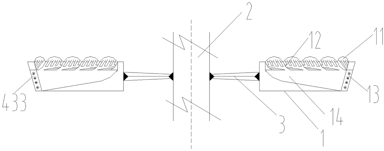
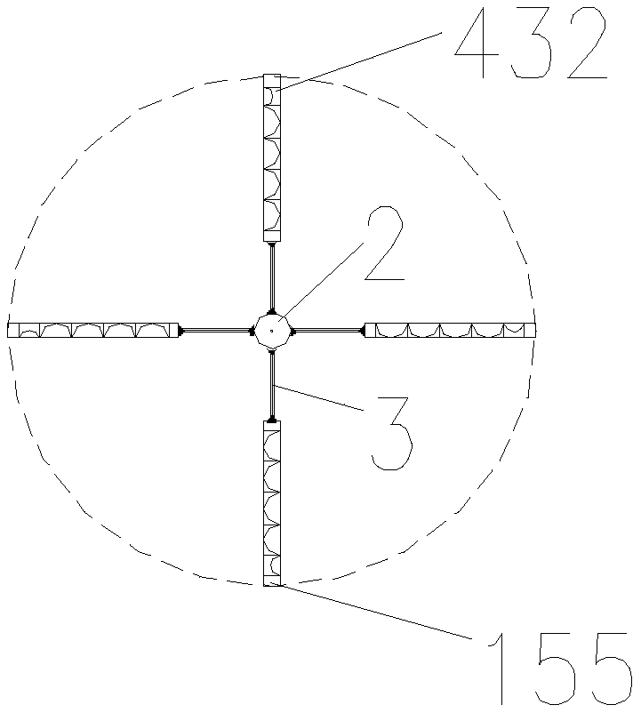
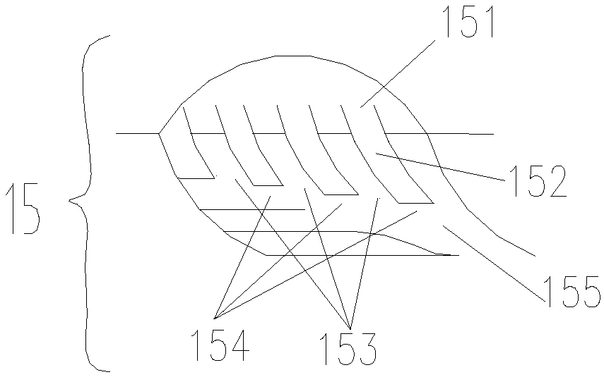
[0016] Figure 1-3 As shown, a multi-stage injection speed-increasing dust collection device includes: a circulating cyclone uniform distribution mechanism 1, a rotating shaft 2, and a supporting shaft 3. The circulation cyclone uniform distribution mechanism 1 passes through and the support shaft 3 stirs and evenly distributes on the rotating shaft 3 . The circulating cyclone uniform distribution mechanism 1 is provided with a wind flow collection port 11, a wind flow diversion channel 12, a secondary air flow outlet 13, a wind flow mixed flow area 14, and a multi-stage ejection speed-up mechanism 15; the wind flow collection port 11 is located at The upper end of the wind flow diversion channel 12 corresponds...


PUM


Abstract

The invention belongs to the field of dedusting process equipment, and concretely relates to a multi-stage ejecting speed-increasing dust-collecting device. A circulating cyclone distributing mechanism provided by the invention can make the circulating wind to form the homodromous accelerating wind flow, so that the dust which is taken away due to the inflow velocity exceeding the critical air inlet air velocity can be removed again, which helps to improve the dust removing effect. A multi-stage ejecting speed-increasing mechanism provided by the present invention provides ejecting power through the inflow stream according to the speed difference in the radial direction of the material, the dust in a diversion channel is driven to form a stepwise ejecting, the discharge of the circulatingdust is accelerated, and the dust removal efficiency and the dust removal effect can be increased.

Description


Claims


Application Information

Patent Timeline
Owner ANHUI UNIV OF SCI & TECH
Why Eureka
Try Eureka