Driving shaft and driven shaft centering device for agricultural machinery
A centering device and agricultural machinery technology, applied in the field of agricultural machinery, can solve the problems of difficulty in popularization, lack of simultaneous calibration of two-axis radial deviation and axial tilt, high price, etc., to increase calibration accuracy, increase calibration flexibility, reduce Effect of Small Calibration Difficulty
Inactive Publication Date: 2019-01-22
NORTHWEST A & F UNIV
View PDF0 Cites 12 Cited by
- Summary
- Abstract
- Description
- Claims
- Application Information
AI Technical Summary
Problems solved by technology
The laser alignment instrument has the advantage of high accuracy, but it is expensive and difficult to popularize in agricultural machinery. In the dial gauge measurement method, there is no device for simultaneously calibrating the two-axis radial deviation and axial tilt
Method used
View moreImage
Smart ImageViewing Examples

Examples
Embodiment Construction
Login to View More PUM
 Abstract
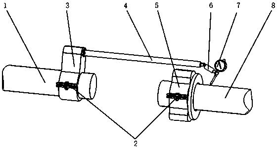
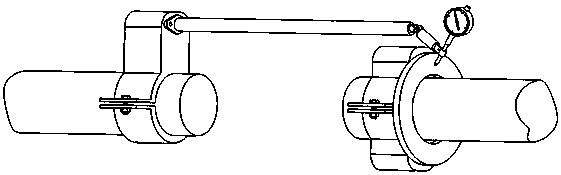
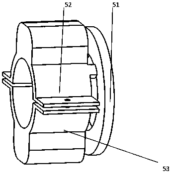
The invention discloses a driving shaft and driven shaft centering device for agricultural machinery. The driving shaft and driven shaft centering device comprises a driving shaft fixing part (5), a driven shaft fixing part (3), a fixed long rod (4), a rotary short rod (6) and a dial indicator (7). When two shafts are centered, the axes of the fixed long rod (4), the rotary short rod (6) and a dial indicator probe (71) and the axis of a driven shaft (1) are positioned on the same plane. When the dial indicator probe (71) slidably contacts with the disk face of a disk (51) with holes, the driven shaft (1) is turned to obtain a measured value of the dial indicator (7), and axial inclination of the two shafts is determined after analysis. When the dial indicator probe (71) slidably contacts with a driving shaft (8), the driven shaft (1) is turned to obtain the measured value of the dial indicator (7), and radial inclination of the two shafts is determined after analysis. The centering device can rapidly check coaxiality of the driving shaft and the driven shaft in power transmission machinery, and is low in cost and high in accuracy.
Description
technical field The invention relates to the technical field of agricultural machinery, in particular to a centering device for calibrating the coaxiality of a driving shaft and a driven shaft in a power transmission system of an agricultural machinery. Background technique In agricultural production, in order to ensure the normal operation of the driven equipment driven by the driving equipment, the centerlines of the driving shaft and the driven shaft should be on the same straight line. When installing the driving equipment and driven equipment, the driving shaft and the driven shaft must be aligned. Find the center. Absolute coaxiality is difficult to achieve. The center deviation of the two shafts mainly includes radial deviation and axial tilt, that is, the two shafts are neither concentric nor parallel. In order to eliminate the deviation, generally after the center line of the driven machine is fixed and leveled , carry out the alignment of the driving shaft and the...
Claims
Login to View More Application Information
Patent Timeline
 IPC IPC(8): B23P19/10G01B5/252
CPCB23P19/10G01B5/252
Inventor 杨福增暴泽明孟宠梁卓
Owner NORTHWEST A & F UNIV
Features
- R&D
- Intellectual Property
- Life Sciences
- Materials
- Tech Scout
- Unparalleled Data Quality
- Higher Quality Content
- 60% Fewer Hallucinations
Learn More Browse by: Latest US Patents, China's latest patents, Technical Efficacy Thesaurus, Application Domain, Technology Topic, Popular Technical Reports.
© 2025 PatSnap. All rights reserved.Legal|Privacy policy|Modern Slavery Act Transparency Statement|Sitemap|About US| Contact US: help@patsnap.com