
Compensation device and compensation method for cutter machining parameters

A technology for processing parameters and processing devices, which is applied in grinding drive devices, metal processing equipment, manufacturing tools, etc., can solve the problems of high labor cost, high production cost, and long time for parameter compensation, so as to reduce production cost, Improve efficiency and reduce the effect of parameter compensation time

Active Publication Date: 2019-01-22
深圳富联智能制造产业创新中心有限公司
View PDF9 Cites 9 Cited by
  • Summary
  • Abstract
  • Description
  • Claims
  • Application Information

AI Technical Summary

Problems solved by technology

[0003] However, the traditional parameter compensation operation needs to rely on the technical experience of technicians, and technicians with corresponding technical experience often need 2 to 3 years of training time, and the labor cost is high; moreover, parameter compensation takes a long time and the efficiency is relatively low. low cost of production

Method used

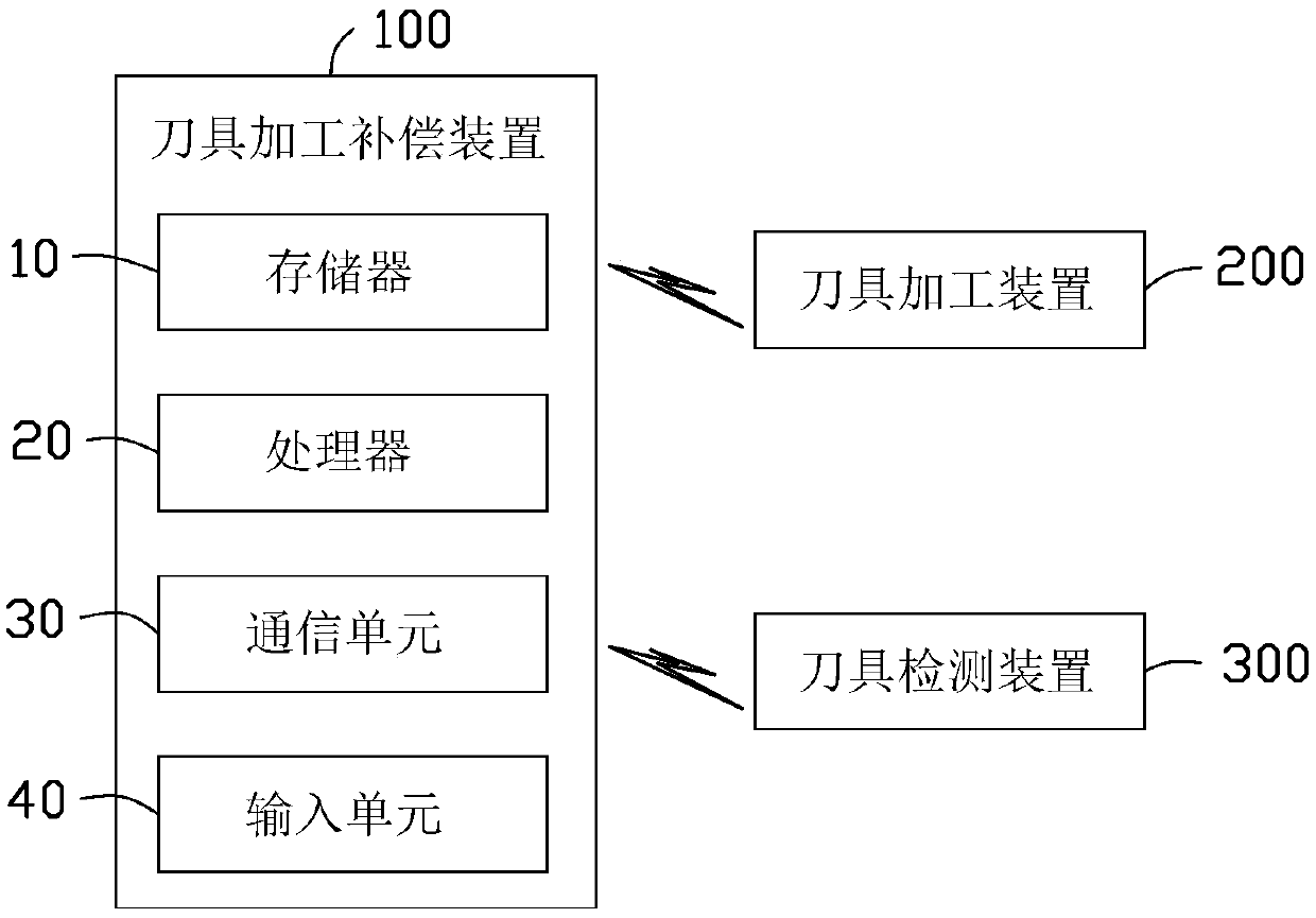

Image

  • Compensation device and compensation method for cutter machining parameters
  • Compensation device and compensation method for cutter machining parameters
  • Compensation device and compensation method for cutter machining parameters

Examples


Embodiment Construction

[0029] In order to better understand the above objects, features and advantages of the present invention, the present invention will be described in detail below in conjunction with the accompanying drawings and specific embodiments. It should be noted that, in the case of no conflict, the embodiments of the present application and the features in the embodiments can be combined with each other.

[0030] In the following description, many specific details are set forth in order to fully understand the present invention, and the described embodiments are only a part of the embodiments of the present invention, but not all of them. Based on the implementation manners in the present invention, all other implementation manners obtained by persons of ordinary skill in the art without making creative efforts belong to the scope of protection of the present invention.

[0031] Unless otherwise defined, all technical and scientific terms used herein have the same meaning as commonly u...


PUM


Abstract

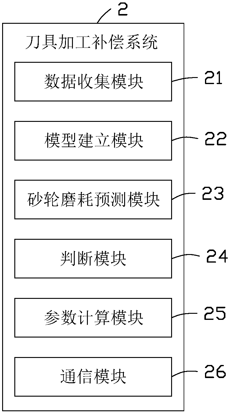
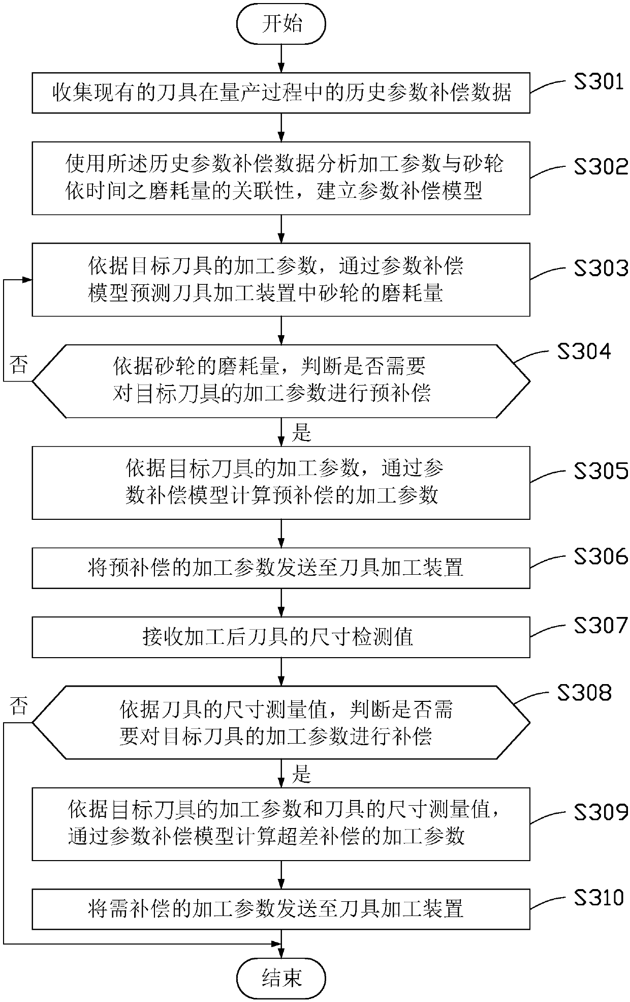
The invention provides a compensation device for cutter machining parameters. The compensation device comprises at least one processor and a memory, the memory memorizes a plurality of modules which are executed by the at least one processer. The modules include: a data acquisition module, a model establishing module, a grinding wheel abrasion predicting module, a judging module, a parameter computing module and a communication module, the data acquisition module is used for acquiring historical parameter compensation data of existing cutters in a mass production process; the model establishing module is used for analyzing relevance between machining parameters and time-based abrasion loss of a grinding wheel according to the historical parameter compensation data and establishing a parameter compensation model; the grinding wheel abrasion predicting module is used for predicting the abrasion loss of the grinding wheel in a cutter machining device; the judging module is used for judging whether the cutter machining parameters need to be compensated or not; the parameter computing module is used for computing the machining parameters which need to be compensated; the communication module is used for transmitting the machining parameters which need to be compensated to the cutter machining device. The invention further provides a compensation method for the cutter machining parameters. By the aid of the compensation device and the compensation method, compensation efficiency of the cutter machining parameters can be improved.

Description

technical field [0001] The invention relates to the technical field of tool processing, in particular to a tool processing parameter compensation device and method. Background technique [0002] At present, precision numerical control sharpening equipment is usually used to process knives. When the tool goes online and starts mass production, the CNC tool grinding equipment completes the forming process of the tool by installing the grinding wheel and executing the grinding program. In actual production, the grinding wheel of CNC knife sharpening equipment will gradually wear out, causing the dimensional error of the machined tool to exceed the tolerance requirements of the engineering drawing, that is, out of tolerance. Therefore, technicians are required to compensate the grinding wheel parameters or program parameters of the CNC knife grinding equipment based on the actual size and tolerance of the tool, combined with technical experience, to eliminate the dimensional er...

Claims


Application Information

Patent Timeline
Patent Type & Authority Applications(China)
IPC IPC(8): B24B3/00B24B47/25
CPCB24B3/00B24B47/25
Inventor 徐龙桂绍文程义群蒋益民李军旗
Owner 深圳富联智能制造产业创新中心有限公司
Learn More