Synthetic aperture radar

a radar and synthetic aperture technology, applied in the field of synthetic aperture radars, to achieve the effect of shortening the time required for motion compensation, shortening the time until the generation of a sar image, and reducing blurring

Active Publication Date: 2020-07-14
MITSUBISHI ELECTRIC CORP
View PDF12 Cites 0 Cited by
  • Summary
  • Abstract
  • Description
  • Claims
  • Application Information

AI Technical Summary

Benefits of technology

[0017]According to the present disclosure, whether or not motion compensation is necessary is determined for each of received radio wave signals on the basis of information on a difference between an planned trajectory and an actual trajectory of a platform, and a motion compensation process is performed on the received radio wave signals for which motion compensation is determined to be necessary. An image generation process is performed on the received radio wave signals on which the motion compensation process has been performed and the received radio wave signals on which the motion compensation process has not be performed depending on the results of determination, so that a SAR image of the observation object is generated. This shortens the time required for motion compensation, and thus shortens the time until generation of a SAR image with blurring reduced by motion compensation.

Problems solved by technology

In a case where the platform is, for example, a flying body such as an aircraft, however, the platform may be affected by wind or the like and follow a trajectory different from the planned trajectory.

Method used


Image

  • Synthetic aperture radar
  • Synthetic aperture radar
  • Synthetic aperture radar

Examples


first embodiment

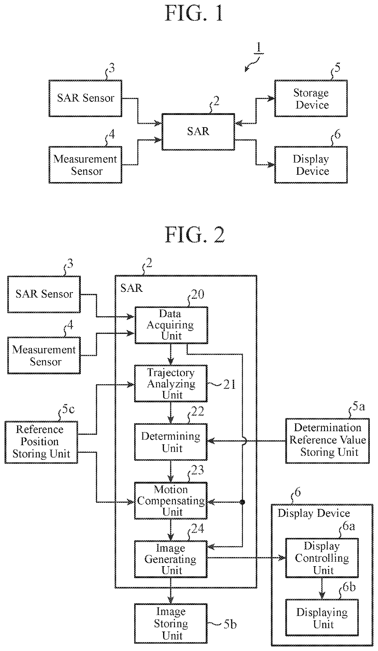
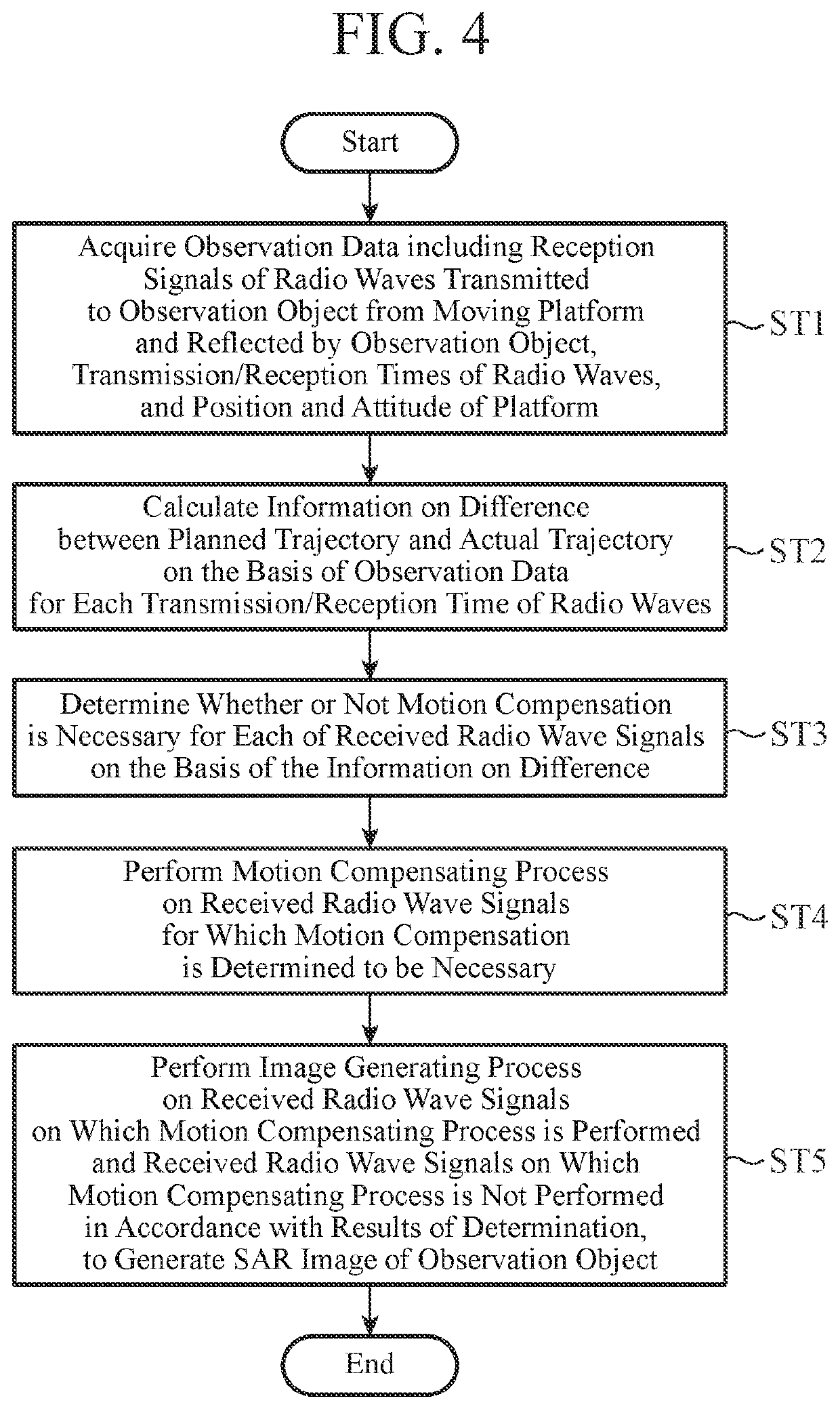
[0037]FIG. 1 is a block diagram illustrating a configuration of a SAR system 1 including a SAR 2 according to the present disclosure. The SAR system 1 is a system for observing the Earth's surface, a sea surface, and the like to obtain a SAR image of an object to be observed, and includes the SAR 2, a SAR sensor 3, a measurement sensor 4, a storage device 5, and a display device 6. The SAR 2 is a device for generating a SAR image of an observation object on the basis of observation data acquired by the SAR sensor 3 and the measurement sensor 4.

[0038]The SAR sensor 3 is a sensing device including a SAR antenna, a transceiver, an analog-to-digital converter, and the like, and is mounted on a platform such as an aircraft or a satellite.

[0039]The SAR sensor 3 emits pulses of radio waves generated by the transceiver into space via the SAR antenna, and receives radio waves reflected by objects to be observed that are present in the space using the SAR antenna.

[0040]The transceiver perform...

second embodiment

[0150]While the configuration for determining whether or not motion compensation is necessary for each of the received radio wave signals transmitted and received during observation has been presented in First Embodiment, a configuration for not only determining whether or not motion compensation is necessary but also selecting a content of the motion compensation process for each of received radio wave signals will be presented in Second Embodiment.

[0151]A SAR according to Second Embodiment will now be described with reference to the observation geometry in FIG. 6.

[0152]FIG. 9 is a block diagram illustrating a configuration of a SAR 2A according to Second Embodiment of the present disclosure. In FIG. 9, components that are the same as those illustrated in FIG. 2 are designated by the same reference numerals.

[0153]The SAR 2A includes a data acquiring unit 20, a trajectory analyzing unit 21, a motion compensating unit 23A, an image generating unit 24, and a selecting unit 25. In addi...

third embodiment

[0198]While First and Second Embodiments are based on the assumption that no measurement error is present in the position and the attitude of the platform 103, a configuration for reducing blurring of a SAR image caused by a measurement error will be described in Third Embodiment.

[0199]FIG. 13 is a block diagram illustrating a configuration of a SAR 2B according to Third Embodiment of the present disclosure. In FIG. 13, components that are the same as those illustrated in FIG. 2 are designated by the same reference numerals. The SAR 2B includes a data acquiring unit 20, a trajectory analyzing unit 21, a determining unit 22, a motion compensating unit 23, an image generating unit 24, and an autofocusing unit 26.

[0200]An autofocus determination reference value storing unit 5e is a storage unit in which an autofocus determination reference value to be used in a process for determining whether or not an autofocusing process is necessary is stored.

[0201]Further, the determination referen...


PUM


Abstract

Whether or not motion compensation is necessary is determined for each of received radio wave signals acquired through observation on the basis of information on a difference between an planned trajectory and an actual trajectory of a platform (103), and a motion compensation process is performed on the received radio wave signals for which the motion compensation is determined to be necessary. An image generation process is performed on the received radio wave signals on which the motion compensation process has been performed and the received radio wave signals on which the motion compensation process has not been performed depending on the results of determination, so that a SAR image of an observation object is generated.

Description

TECHNICAL FIELD[0001]The present disclosure relates to synthetic aperture radars (hereinafter referred to as SAR).BACKGROUND ART[0002]A SAR emits pulses of radio waves repeatedly from a SAR sensor mounted on a platform to objects to be observed, and receives the radio waves that are reflected by the objects. The SAR then generates a SAR image on the basis of position information of the platform acquired when radio waves are transmitted, position information of the platform acquired when the radio waves that are reflected by an object to be observed are received, and received radio wave signals. Note that received signals of radio waves that are transmitted and received while a platform follows a trajectory that is planned (hereinafter referred to as an planned trajectory) are supposed to be used to generate a SAR image.[0003]In a case where the platform is, for example, a flying body such as an aircraft, however, the platform may be affected by wind or the like and follow a trajecto...

Claims


Application Information

Patent Timeline
Patent Type & Authority Patents(United States)
IPC IPC(8): G01S13/90G01S7/40G01S7/04
CPCG01S13/90G01S7/4026G01S7/04G01S13/9019
Inventor OISHI, NOBORU
Owner MITSUBISHI ELECTRIC CORP
Why Eureka
Try Eureka