Composite rotating shaft mechanism

A composite, rotating shaft technology, applied in the direction of supporting machines, mechanical equipment, pivot connections, etc., can solve problems such as high cost, insufficient product competitiveness, and rising cost of SIP phones, achieve low cost, ensure rotation stability and reliability sexual effect

Pending Publication Date: 2019-01-22
XIAMEN YEALINK NETWORK TECH
View PDF4 Cites 1 Cited by
  • Summary
  • Abstract
  • Description
  • Claims
  • Application Information

AI Technical Summary

Problems solved by technology

[0006] At present, the conventional shaft assembly method used in SIP phones is complicated and costly, which leads to an increase in the overall cost of SIP phones and insufficient product competitiveness.

Method used


Image

  • Composite rotating shaft mechanism
  • Composite rotating shaft mechanism
  • Composite rotating shaft mechanism

Examples


Embodiment 1

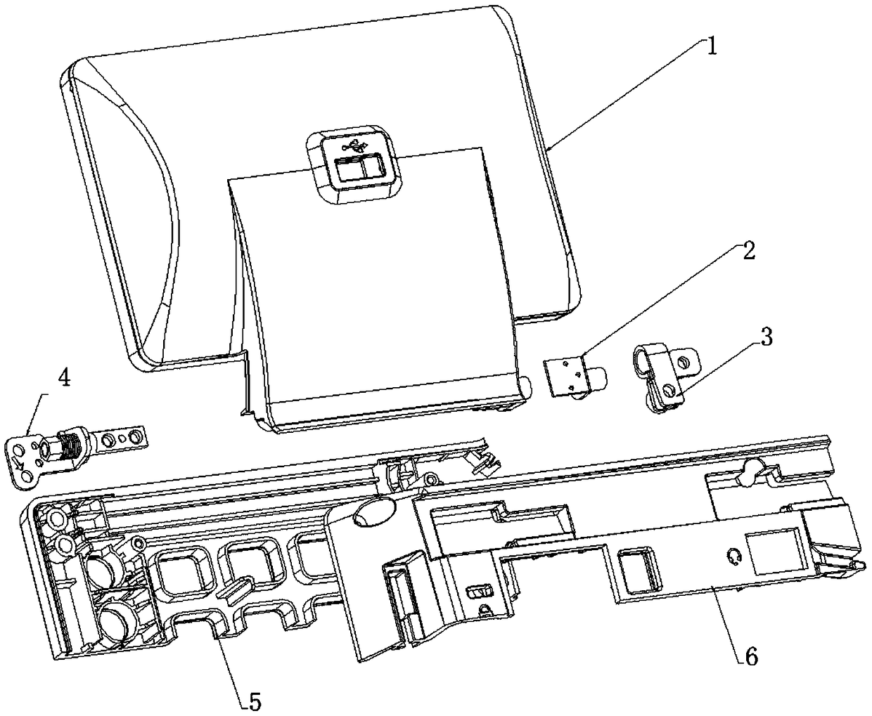
[0045] like figure 1 and figure 2 As shown, the low-cost shift-type rotating shaft mechanism in this embodiment includes the following spare parts: a face shell, a bottom shell, a liquid crystal module, a conventional rotating shaft, a fixing bracket, a reinforcing shaft, and screws.

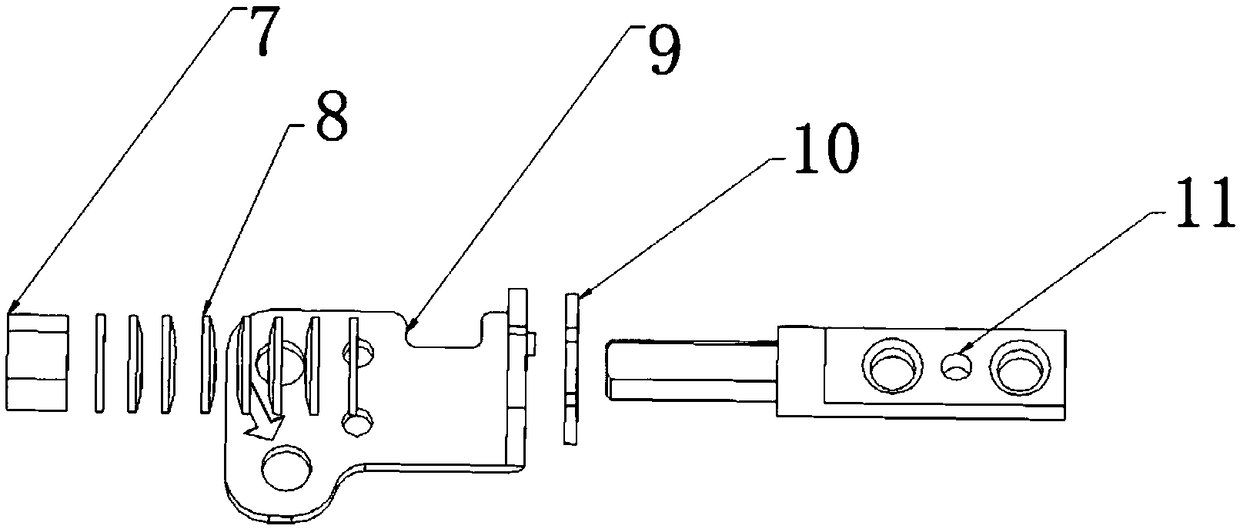
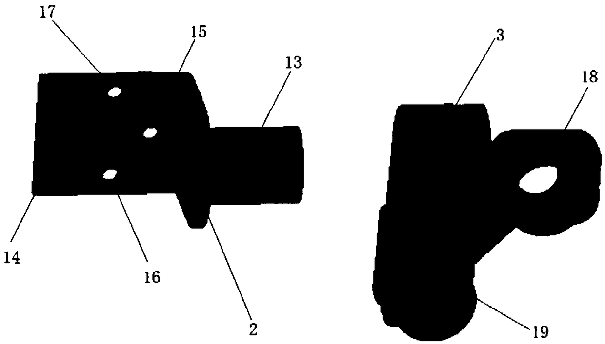
[0046] like figure 2 The fixed bracket shown is a sheet metal part or a high-strength plastic part, and a screw mounting hole and a reinforcement shaft adapter port are provided. The reinforcement shaft adapter port is designed in an Ω shape to facilitate assembly on the reinforcement shaft; The hardware includes a fixed end and a rotating end. The fixed end is provided with three screw mounting holes, which are fixed to the liquid crystal component through screw locks. The rotating end is inserted into the reinforcing shaft adapter port on the fixed bracket; the limiting rotating shaft includes a fastening nut , a spring washer, a movable frame, a spacer and a mandrel, and the mandrel inclu...

Embodiment 2

[0063] An assembly method of a composite rotating shaft mechanism, characterized in that the steps include:

[0064] (1). If figure 2 As shown, assemble the limit shaft and adjust the torque value to meet the design requirements;

[0065] (2). If Figure 4 As shown, fix the conventional rotating shaft on the liquid crystal component through screw locks, and fix the reinforcing shaft on the liquid crystal component through screw locks;

[0066] (3). If Figure 5 As shown, fit the fixing bracket to the reinforcing shaft;

[0067] (4). If Image 6 As shown in the figure, assemble the liquid crystal component on the panel, and lock the rotating shaft and the fixing bracket with screws;

[0068] (5). If Figure 7 As shown, cover the bottom case and fix it with screws.

[0069] In this embodiment, the assembly of the fixing bracket on the reinforcing shaft is specifically as follows:

[0070] like Figure 8 and Figure 9 As shown, the opening of the mounting opening of th...


PUM


Abstract

The invention discloses a composite rotating shaft mechanism. The composite rotating shaft mechanism comprises a face shell, a bottom shell, a liquid crystal assembly, a limit rotating shaft, a fixedsupport, a reinforced shaft, and screws; according to one end of the novel composite rotating shaft mechanism, a routine rotating shaft is fixedly arranged on the liquid crystal assembly and the faceshell, and the other end is provided with a composite rotating shaft structure; the reinforced shaft is adopted for cooperation with the fixed support, so that double-shaft stability and reliability are achieved. The composite rotating shaft mechanism is low in cost, is capable of solving a problem in the prior art that cost is relatively high because of adoption of double rotating shafts in a conventional rotating shaft assembling method; different display angles can be achieved through rotating of the liquid crystal assembly by users; the assembling mode is simple; complex assembling requirements of routine rotating shafts are avoided; and product comprehensive competition advantages are improved greatly.

Description

technical field [0001] The invention relates to the field of rotating display panel rotating products of telephone sets, in particular to a composite rotating shaft mechanism. Background technique [0002] Because different users of SIP phone products have different display angle requirements, the liquid crystal display part needs to be made to be able to rotate. SIP phone products generally use conventional hinges; specifically, two conventional hinges are used to fix the LCD panel and the cover respectively. In order to ensure stability and reliability, hinges are used at both ends. In this way, the user can achieve the purpose of rotating the liquid crystal panel by rotating the liquid crystal part, so as to realize different display angle requirements. When using the phone, adjust the liquid crystal panel to rotate up and down to a rotation position that meets the user's usage habits, so as to realize the information on the panel when talking on the phone. [0003] Gen...

Claims


Application Information

Patent Timeline
Patent Type & Authority Applications(China)
IPC IPC(8): F16C11/04F16C11/10F16C11/12F16M11/10
CPCF16C11/04F16C11/10F16C11/12F16M11/10
Inventor 任东平黄楷文
Owner XIAMEN YEALINK NETWORK TECH
Why Eureka
Try Eureka