A fault diagnosis method and a system based on a hot standby redundant display

A diagnostic method and diagnostic system technology, which is applied to the redundancy of hardware for data error detection, instrumentation, and response errors, etc., to achieve the effect of reducing serious consequences

Active Publication Date: 2019-01-22
HUNAN CRRC TIMES SIGNAL & COMM CO LTD
View PDF12 Cites 2 Cited by
  • Summary
  • Abstract
  • Description
  • Claims
  • Application Information

AI Technical Summary

Problems solved by technology

If the fault can be found in a short period of time and the switch can be performed in time, the probability of failure of the entire system can be reduced. However, there is currently no such method or system that can detect faults in time.

Method used


Image

  • A fault diagnosis method and a system based on a hot standby redundant display
  • A fault diagnosis method and a system based on a hot standby redundant display
  • A fault diagnosis method and a system based on a hot standby redundant display

Examples


Embodiment Construction

[0031] The present invention will be described in detail below in conjunction with the accompanying drawings and specific embodiments. Note that the aspects described below in conjunction with the drawings and specific embodiments are only exemplary, and should not be construed as limiting the protection scope of the present invention.

[0032] Figure 4 The flowchart of an embodiment of the method for diagnosing faults based on hot standby redundant displays of the present invention is shown. See Figure 4 , the following is a detailed description of the implementation steps of the diagnostic method of this embodiment.

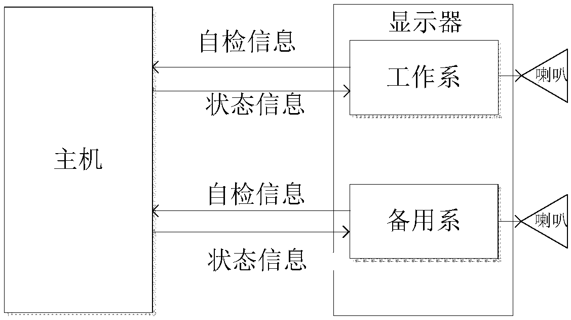
[0033] Step S1: The host computer respectively receives the self-test information sent by the working system and the standby system of the display.

[0034] Such as figure 1 As shown, the display is divided into a working system and a standby system under normal working conditions, and the working system and the standby system periodically send self-test ...


PUM


Abstract

The invention discloses a fault diagnosis method and a system based on a hot standby redundant display, which can self-diagnose the fault and prompt to reduce the fault probability of the whole machine. The technical scheme comprises the following steps: the host computer judges whether the status is normal or not through the self-test information sent by the display working system and the standbysystem; when the working system fails, the host computer sends the status information of the failure to the standby system for fault prompt to switch the system, so as to reduce the serious consequences caused by the failures.

Description

technical field [0001] The invention relates to a device fault diagnosis technology, in particular to a fault diagnosis method and system based on hot standby redundant display. Background technique [0002] The hot standby redundant display is a display with two sets of software and hardware working at the same time. Due to its redundancy, the security and availability of the display are greatly enhanced compared with a single set of software and hardware design. Two sets of software and hardware work at the same time, divided into working system and standby system. The work department is responsible for human-computer interaction (keyboard input, touch input, voice output, graphic output) and communication with the host. By switching the switch, you can switch between the working system and the standby system. [0003] In the actual use process, it is up to the user to judge whether the working system is faulty, and if the working system is faulty, it is manually switche...

Claims


Application Information

Patent Timeline
Patent Type & Authority Applications(China)
IPC IPC(8): G06F11/20G06F11/32
CPCG06F11/2023G06F11/321
Inventor 刘海军盘宇王业流唐林彭哲徐王强陈泽华蒋春雷刘辉祝国锦
Owner HUNAN CRRC TIMES SIGNAL & COMM CO LTD
Why Eureka
Try Eureka