

Car rear-end collision prevention method and car rear-end collision prevention device
A technology for preventing rear-end collisions and cars. It is applied in transportation and packaging, vehicle components, and vehicle safety arrangements to reduce serious consequences and protect safety.
- Summary
- Abstract
- Description
- Claims
- Application Information
AI Technical Summary
Problems solved by technology
Method used
Image

Examples
Embodiment 1
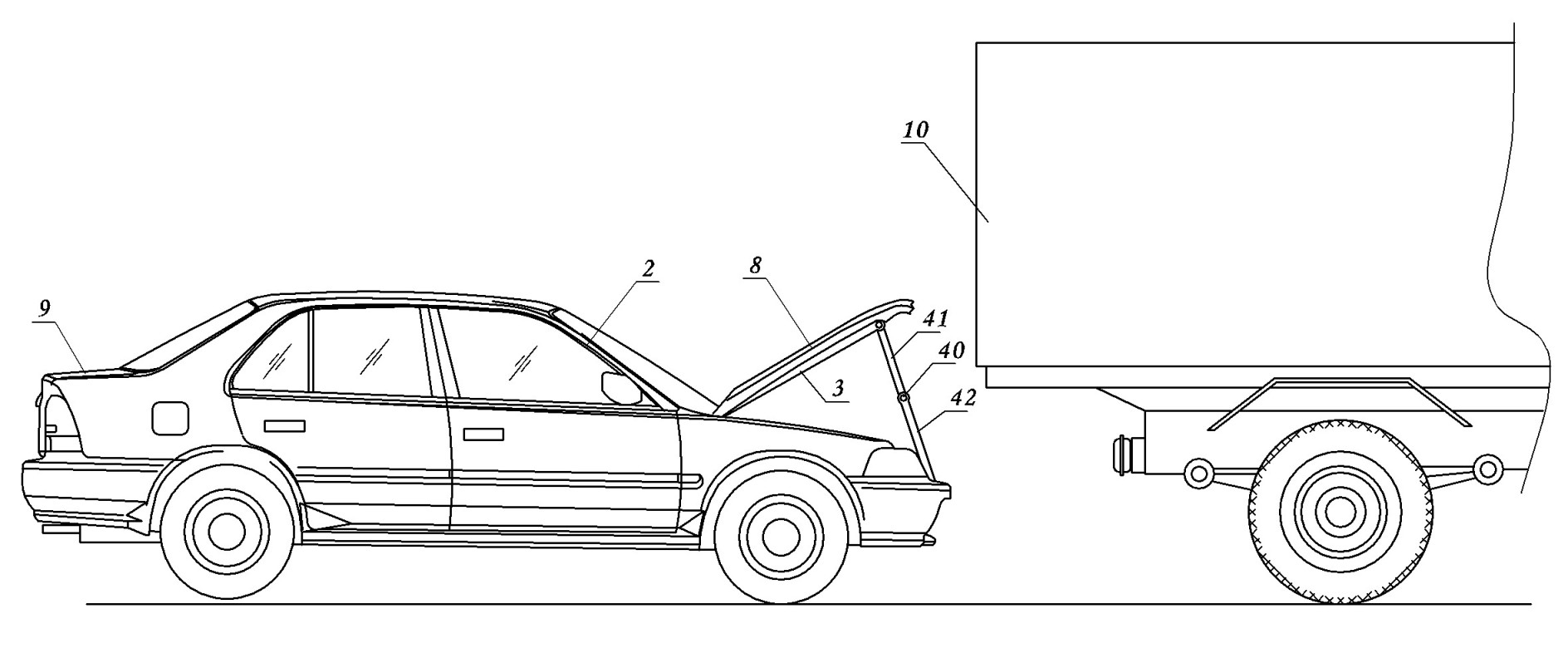
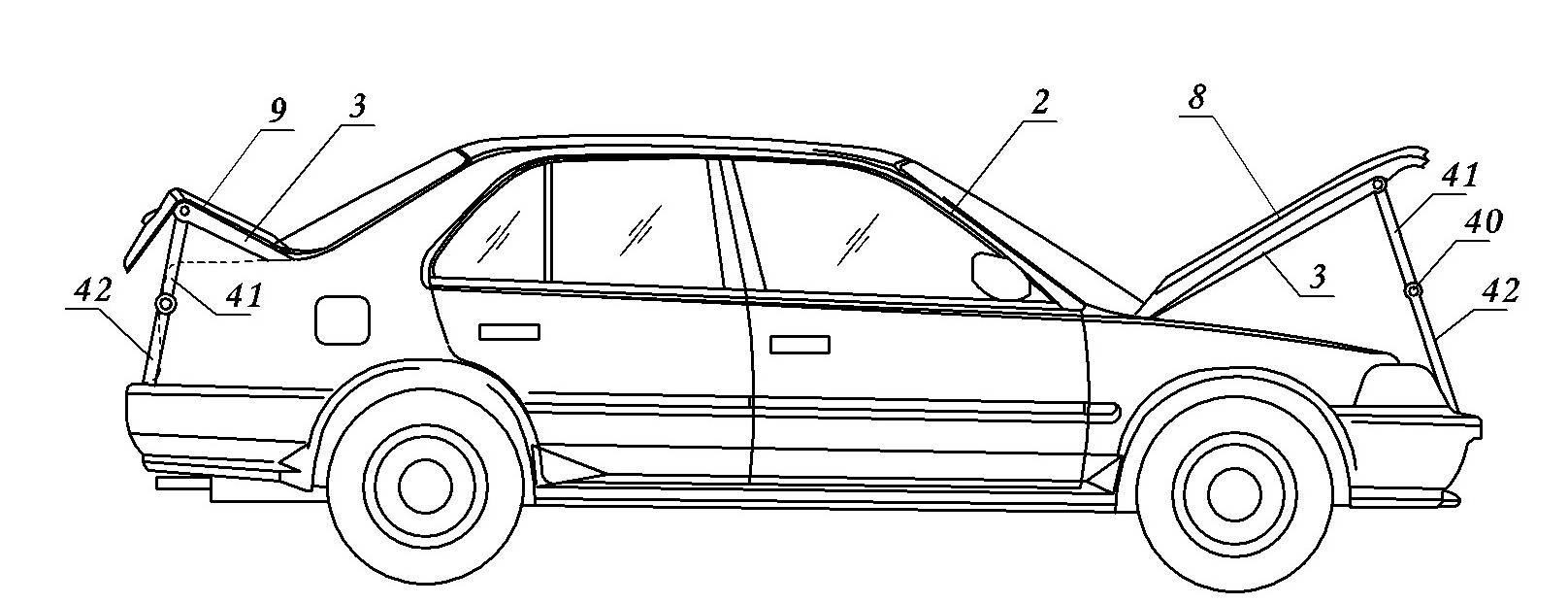
[0030] Embodiment one: see figure 1 — Figure 9 , Figure 12 with Figure 13 , a method for preventing rear-end collision of a car, the method is to hinge a support rod on the front window frame column (A-pillar) in the hood, and hinge a pull rod or a pull rope (wire rope or chain) at the front end of the support rod, the pull rod At least one rotating shaft is arranged in the middle part to form a flexible connection structure. In the present invention, the angle range between the pull rod or the pull rope and the support rod after straightening is between 45° and 120°, which can ensure that the pull rod or pull rope first directly contacts the cart to generate pulling force when it collides. The best pulling effect can be achieved when the range of the included angle is close to 90 degrees, so an included angle in the range of 60 degrees to 90 degrees is preferred. The lower end of said pull rod or stay rope is hinged on the front end of the car frame.
[0031] Use the ...
Embodiment 2
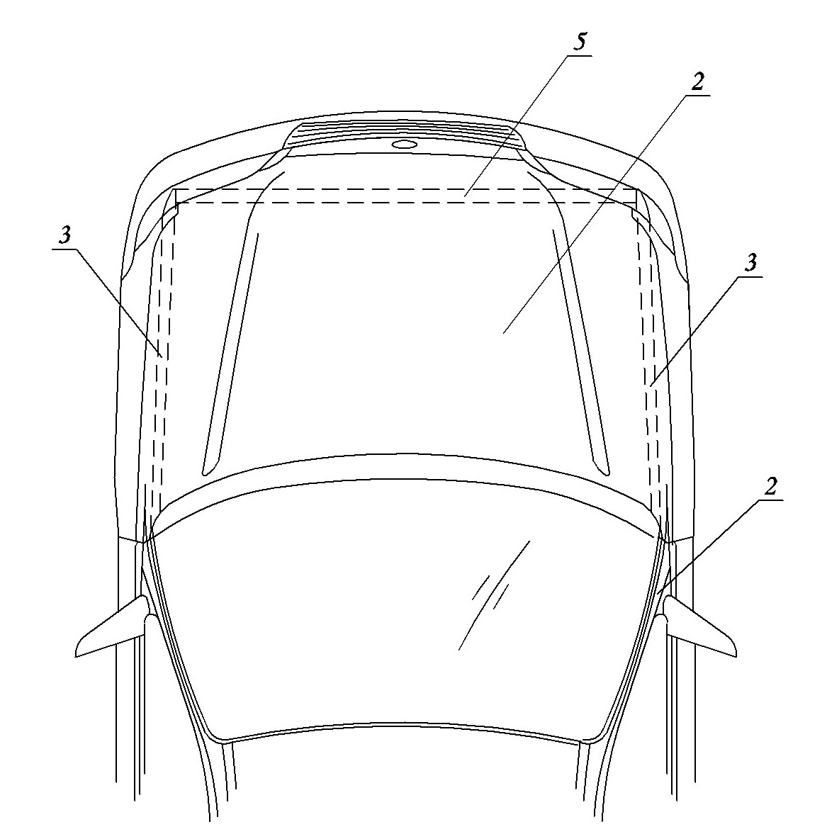
[0036] Embodiment two: see figure 1 , image 3 — Image 6 , Figure 12 with Figure 13 , a car anti-rear-collision device, the two sides in the engine cover 8 are respectively hidden with a support rod 3, the support rod 3 and the direction of the engine cover 8 both sides are basically consistent to facilitate hiding and giving way. In the present embodiment, the support rod 3 is fixed below the engine, and the rear end of the support rod 3 is located near the engine cover 8 hinges, and can be welded together with the upper page of the hinge. The front end of the support rod 3 is hinged with a pull rod, and the pull rod includes The upper section 41 and the lower section 42, and the middle parts of the upper and lower sections are connected together by a rotating shaft 40, so that the pull bar becomes foldable. The lower ends of the pull rods on both sides are hinged on the front end of the car frame 1. Thereby, the vehicle frame, the supporting rod, and the distance bet...
Embodiment 3
[0038] Embodiment three: see figure 1 , Figure 7 — Figure 9 , Figure 12 with Figure 13 , the content is basically the same as that of Embodiment 1, and the similarities will not be repeated. The difference is that the pull rod is changed into a stay rope (wire rope or chain).
PUM
| Property | Measurement | Unit |
|---|---|---|
| Angle | aaaaa | aaaaa |
| Angle | aaaaa | aaaaa |
Abstract
Description
Claims
Application Information