Separation apparatus of waste magnetic construction material

A separation device and building material technology, applied in magnetic separation, solid separation, chemical instruments and methods, etc., can solve the problems of automatic collection of materials, easy to generate danger, etc., and achieve the effect of convenient absorption

Active Publication Date: 2019-01-25
SHANDONG HUABANG CONSTR GRP
View PDF9 Cites 1 Cited by
  • Summary
  • Abstract
  • Description
  • Claims
  • Application Information

AI Technical Summary

Problems solved by technology

[0002] For example, the patent number is CN201720471773.7, a resin-based composite material separation device for plastic processing plants, including a box, etc., but the disadvantage of this invention is that there is no way to automatically collect the separated materials. If it is necessary to separate toxic materials In the process of collecting materials, it is easy to cause danger

Method used


Image

  • Separation apparatus of waste magnetic construction material
  • Separation apparatus of waste magnetic construction material
  • Separation apparatus of waste magnetic construction material

Examples


specific Embodiment approach 1

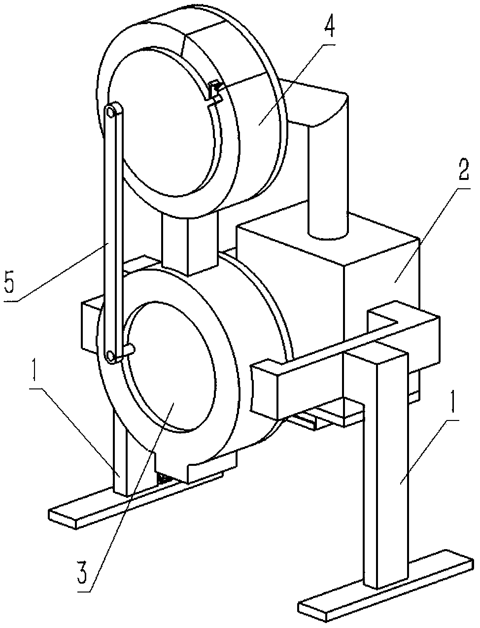
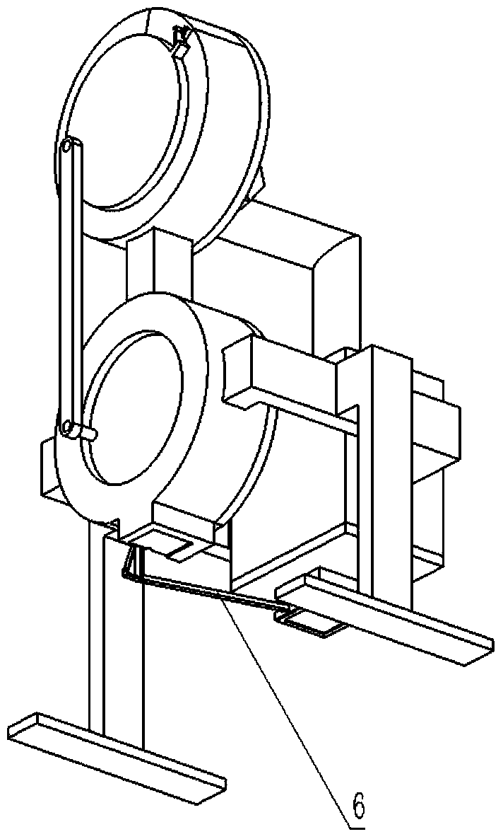
[0042] Combine below Figure 1-23 Describe this embodiment, a separation device for waste magnetic building materials, including two bottom frames 1, a magnetic discharge device 2, a non-magnetic material discharge device 3, a separation device 4, a connecting rod 5 and a lower connecting rod 6, The front and rear ends of the two chassis 1 are fixedly connected to the front and rear ends of the separation device 4 and the non-magnetic material discharge device 3, the separation device 4 is fixedly connected to the upper end of the non-magnetic material discharge device 3, and the non-magnetic The material discharging device 3 communicates with the separating device 4 , the connecting rod 5 is connected between the separating device 4 and the connecting rod 5 , and the lower connecting rod 6 is connected between the magnetic discharging device 2 and the non-magnetic material discharging device 3 .

specific Embodiment approach 2

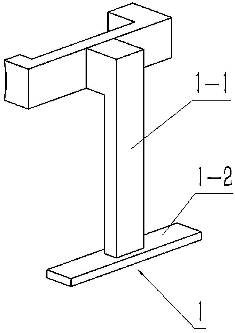
[0043] Combine below Figure 1-23 This embodiment will be described, and this embodiment will further describe Embodiment 1. The chassis 1 includes a support rod 1-1 and a bottom plate 1-2, and the bottom plate 1-2 is fixedly connected to the lower end of the support rod 1-1.

specific Embodiment approach 3

[0044] Combine below Figure 1-23 Describe this embodiment, this embodiment will further explain the second embodiment, the magnetic discharge device 2 includes a magnetic discharge outer frame 2-1, a connecting pipe 2-2, a lower terminal 2-3, a magnetic closing plate 2- 4. The chute 2-5 and the end plate 2-6, the inner end of the magnetic discharge outer frame 2-1 is hollowed out, the connecting pipe 2-2 is fixedly connected to the upper end of the magnetic discharge outer frame 2-1, and the magnetic discharge The outer frame 2-1 communicates with the connecting pipe 2-2, the lower terminal 2-3 is fixedly connected to the lower end of the magnetic discharge outer frame 2-1, the chute 2-5 is arranged at the lower end of the lower terminal 2-3, and the magnetic closing plate 2 -4 is slidingly connected in the magnetic closing plate 2-4, the end plate 2-6 is fixedly connected to the front end of the magnetic closing plate 2-4, and the rear ends of the two struts 1-1 are respecti...


PUM


Abstract

The invention relates to a separation apparatus of a construction material, in particular to a separation apparatus of a waste magnetic construction material. The separation apparatus can be used forautomatically collecting separated materials. The separation apparatus comprises two bottom frames, a magnetic discharging apparatus, a nonmagnetic material discharging apparatus, a separation apparatus, a connecting rod and a lower side connecting rod, wherein inner ends of a magnetic discharging outer frame and a communicating pipe are respectively hollowed, so that the magnetic discharging outer frame can be communicated with the communicating pipe; a sliding groove can facilitate the sliding connection of a magnetic closing plate; an end plate can limit a rear end of the magnetic closing plate in the sliding groove, so that the magnetic closing plate is not separated from the sliding groove; a material outlet hole can be conveniently communicated with a rectangular sliding groove; a sliding rod can be conveniently hinged with the lower side connecting rod; a gravity core of a cavity is located on an eccentric position of the axis of an outer frame casing pipe, so that the nonmagnetic material collected in the cavity can flow out of a notch; and two limiting casing pipes can limit the sliding connection of two inner sliding columns in two sliding holes, so that the inner slidingcolumn can be prevented from being separated from the sliding hole.

Description

technical field [0001] The invention relates to a separation device for building materials, in particular to a separation device for waste magnetic building materials. Background technique [0002] For example, the patent number is CN201720471773.7, a resin-based composite material separation device for plastic processing plants, including a box, etc., but the disadvantage of this invention is that there is no way to automatically collect the separated materials. If it is necessary to separate toxic materials In the process of collecting materials, it is easy to cause danger. The bottom of the box is equipped with an anti-sticking wall mechanism and a sloping plate. The anti-sticking wall mechanism is located under the sloping plate. The left side of the box is equipped with a blanking mechanism. Stirring mechanism, the stirring mechanism of this device continuously disperses the resin material, so as to improve the separation efficiency and make the separation effect bette...

Claims


Application Information

Patent Timeline
Patent Type & Authority Applications(China)
IPC IPC(8): B03C1/02
CPCB03C1/02
Inventor 刘丽军
Owner SHANDONG HUABANG CONSTR GRP
Why Eureka
Try Eureka