Supporting device for constructional engineering

A technology of support device and construction engineering, which is applied in construction, building structure, and on-site preparation of building components, etc., can solve the problems affecting the use of the support frame, poor support stability, fixed support area, etc., and achieves a simple and convenient sliding-out distance. , High support stability, the effect of improving stability

Inactive Publication Date: 2019-10-29
湖北元邦建筑工程有限公司
View PDF7 Cites 1 Cited by
  • Summary
  • Abstract
  • Description
  • Claims
  • Application Information

AI Technical Summary

Problems solved by technology

[0004] The purpose of the present invention is to provide a support device for construction engineering, to solve the problem that the support frame for traditional construction engineering proposed in the above-mentioned background technology is mostly in the form of a single support plate, the support area is fixed, and the support stability is relatively poor, which affects the use of construction engineering. The use of support frames also affects the safety of construction engineering supports, and the specifications of support columns are mostly fixed. For construction engineering supports of different heights, it is necessary to replace support columns with different specifications. The replacement is time-consuming and laborious, which affects the support frames used in construction projects. Ease of use problem

Method used


Image

  • Supporting device for constructional engineering
  • Supporting device for constructional engineering
  • Supporting device for constructional engineering

Examples


Embodiment Construction

[0016] The following will clearly and completely describe the technical solutions in the embodiments of the present invention with reference to the accompanying drawings in the embodiments of the present invention. Obviously, the described embodiments are only some, not all, embodiments of the present invention. Based on the embodiments of the present invention, all other embodiments obtained by persons of ordinary skill in the art without making creative efforts belong to the protection scope of the present invention.

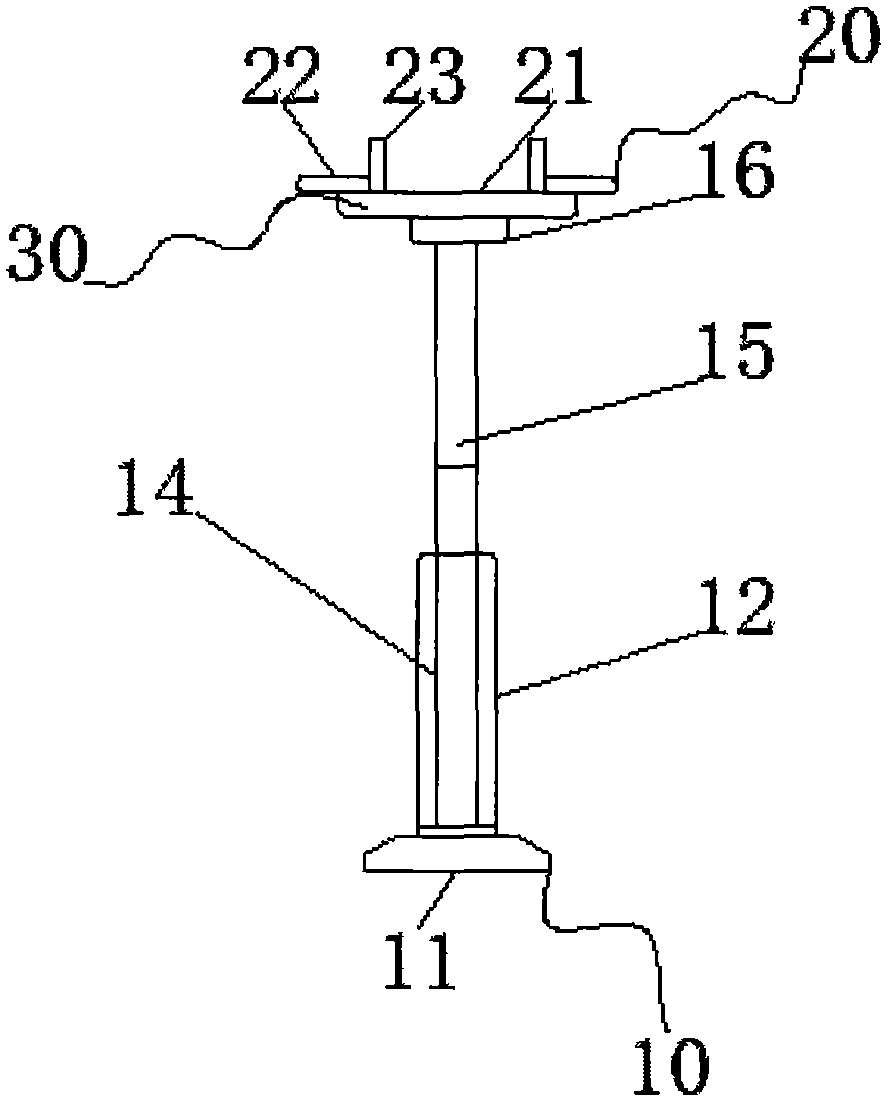
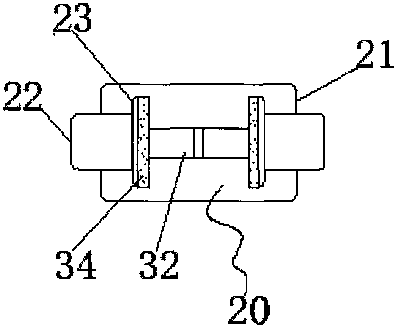
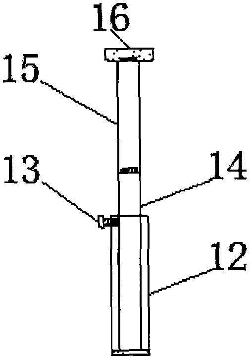
[0017] see Figure 1-4 , the present invention provides a technical solution: a support device for construction engineering, including a housing assembly 10, a support assembly 20 and an adjustment assembly 30, the housing assembly 10 includes a base 11, a support column 12, a sliding column fixing rod 13, a first sliding The column 14, the second sliding column 15 and the main fixing seat 16, the supporting column 12 is located on the upper surface of the bas...


PUM


Abstract

The invention discloses a supporting device for constructional engineering. The supporting device comprises a casing assembly, a supporting assembly and an adjusting assembly; the adjusting assembly comprises a sliding rail, an auxiliary supporting plate and a sliding block fixing rod; the sliding rail is located on the lower surface of the interior of a main supporting plate and fixedly connectedwith the main supporting plate; the auxiliary supporting plate is located on the left side of the upper surface of the sliding rail and slidably connected with the sliding rail; the sliding block fixing rod penetrates through a sliding block and is fixedly connected with the sliding block; and by arranging the sliding rail, the auxiliary supporting plate arranged in the main supporting plate is conveniently and slidably connected, the lateral support area is freely adjusted, thus the supporting device adapts to different construction engineering for support, by arranging an auxiliary side supporting plate, a main side supporting plate is conveniently and slidably connected, the longitudinal supporting area is freely adjusted, the stability of a support frame for construction engineering is further improved, and by arranging the sliding block fixing rod and side supporting plate fixing rods, fixing sliding blocks and the auxiliary supporting plate are conveniently connected with the main side supporting plate and the auxiliary side supporting plate in a threaded mode.

Description

technical field [0001] The invention belongs to the technical field of supporting devices, and in particular relates to a supporting device for construction engineering. Background technique [0002] The basis of the building support frame is the formwork support system. The formwork support system consists of three series: the roof formwork support composite structure, the frame column formwork support composite structure, and the shear wall formwork support composite structure. The three sets of systems are flexible in combination and tight in structure. According to the different requirements of each project of the customer, it is designed and configured, which has the advantages of energy saving, material saving, cost saving, project quality assurance, and construction efficiency improvement. [0003] The support frame used in traditional construction engineering is mostly used to support the baffle and fix the uncured cement. It is widely used in the support of construc...

Claims


Application Information

Patent Timeline
IPC IPC(8): E04G25/06
CPCE04G25/06
Inventor 王养
Owner 湖北元邦建筑工程有限公司
Why Eureka
Try Eureka