Adaptor for connecting a cannula to a gas machine

a technology for adaptors and gas machines, applied in the field of surgical instruments, can solve the problems of affecting the function of trocars and being relatively expensive, and achieve the effects of preventing easy detachment low cost, and convenient sliding attachment of the distal end

Inactive Publication Date: 2013-08-13
TEVES LEONIDES Y
View PDF12 Cites 1 Cited by
  • Summary
  • Abstract
  • Description
  • Claims
  • Application Information

AI Technical Summary

Benefits of technology

[0021]In all embodiments, a small gas-access opening is formed in the nipple and a compression fitting extends snugly through said gas-access opening. The fitting includes a base having a diameter substantially greater than a diameter of the gas-access opening and a post formed integrally with the base. The post has a diameter greater than a diameter of the lumen of the elongate hose. The base is positioned within the space defined by the disc-shaped hub and the nipple and the post is positioned externally of the nipple. At least one annular ridge is formed on the post and is angled to facilitate sliding attachment of the distal end of the elongate hose onto the post but to prevent facile detachment of the distal end from the post.
[0022]An important object of the invention is to provide a low cost way of interconnecting a gas machine and a cannula.

Problems solved by technology

This defeats the purpose of a trocar which is to minimize multiple withdrawals and insertion of instruments through an incision.
Adaptors for interconnecting the hose to a proximal end of the cannula are commercially available, but they are relatively expensive because they are made from multi-cavity molds.

Method used


Image

  • Adaptor for connecting a cannula to a gas machine
  • Adaptor for connecting a cannula to a gas machine
  • Adaptor for connecting a cannula to a gas machine

Examples


first embodiment

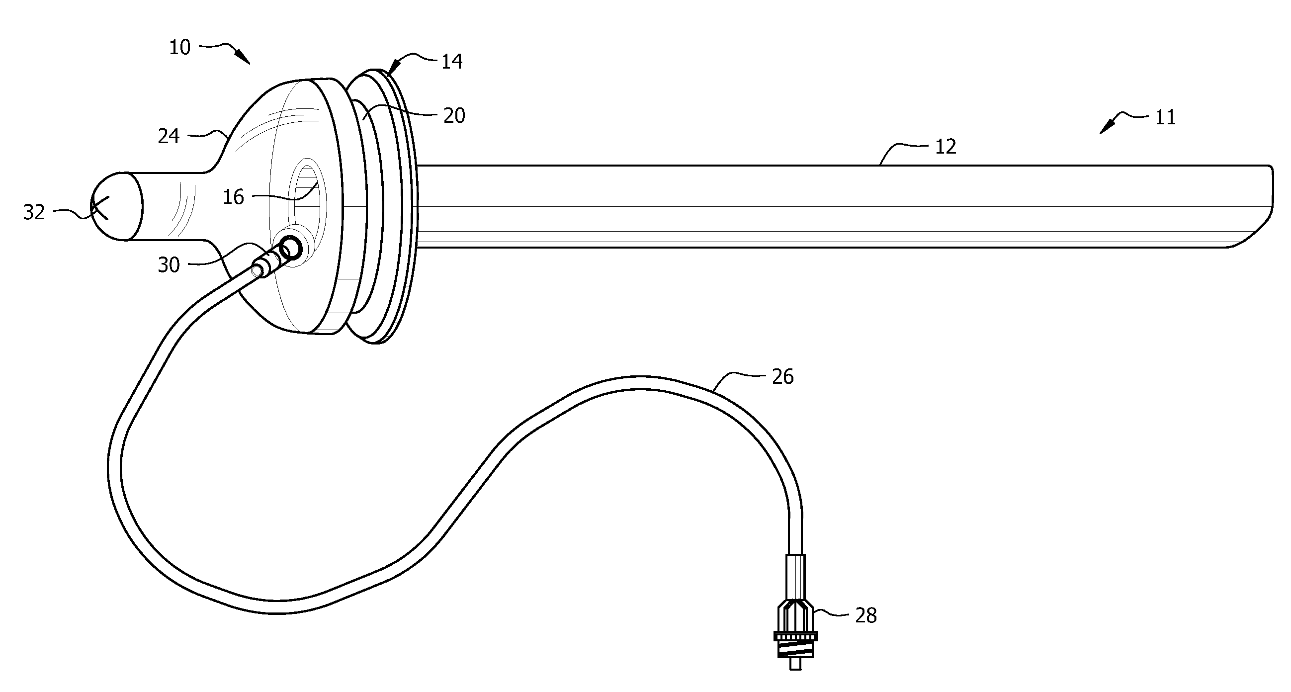
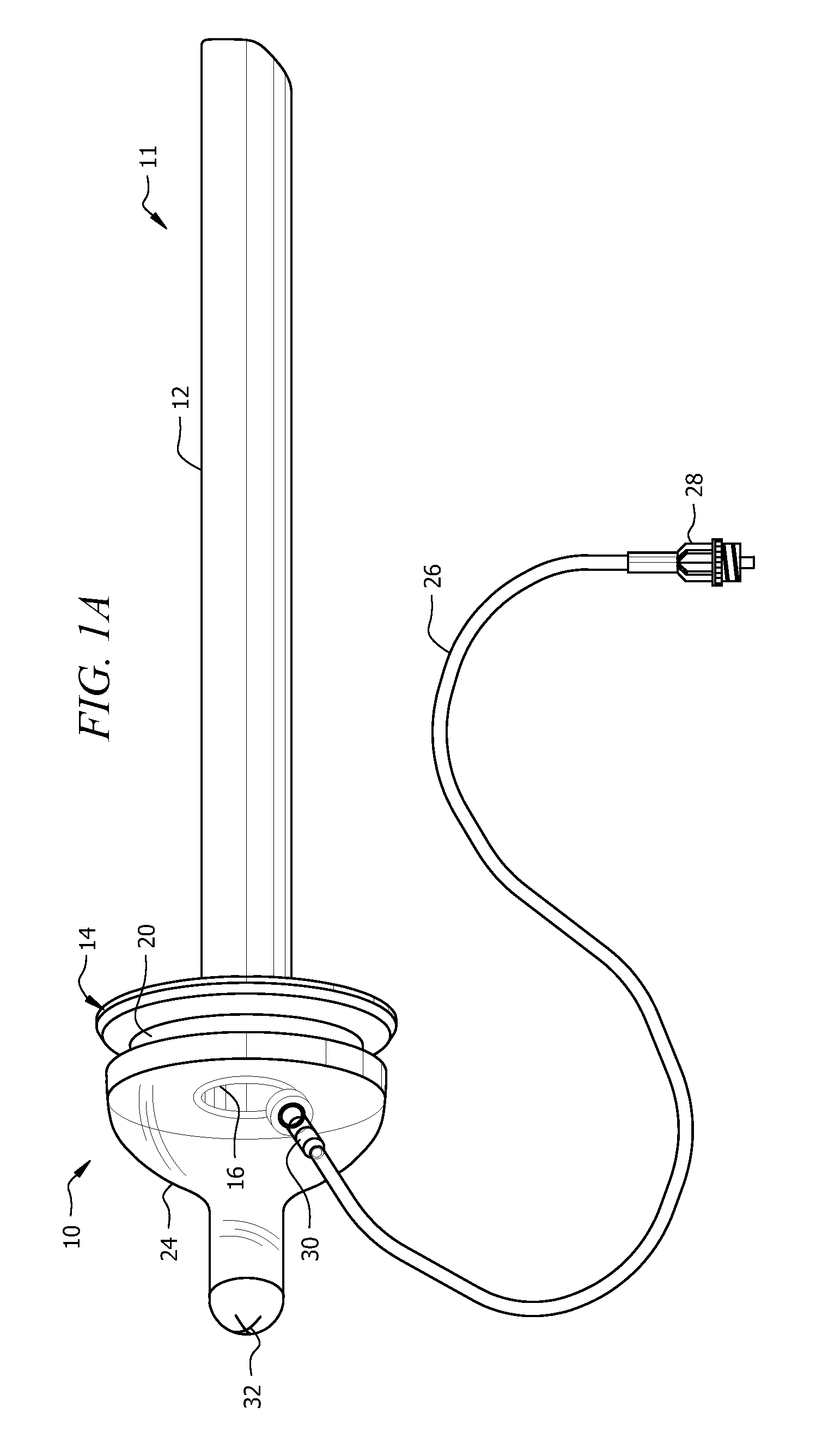
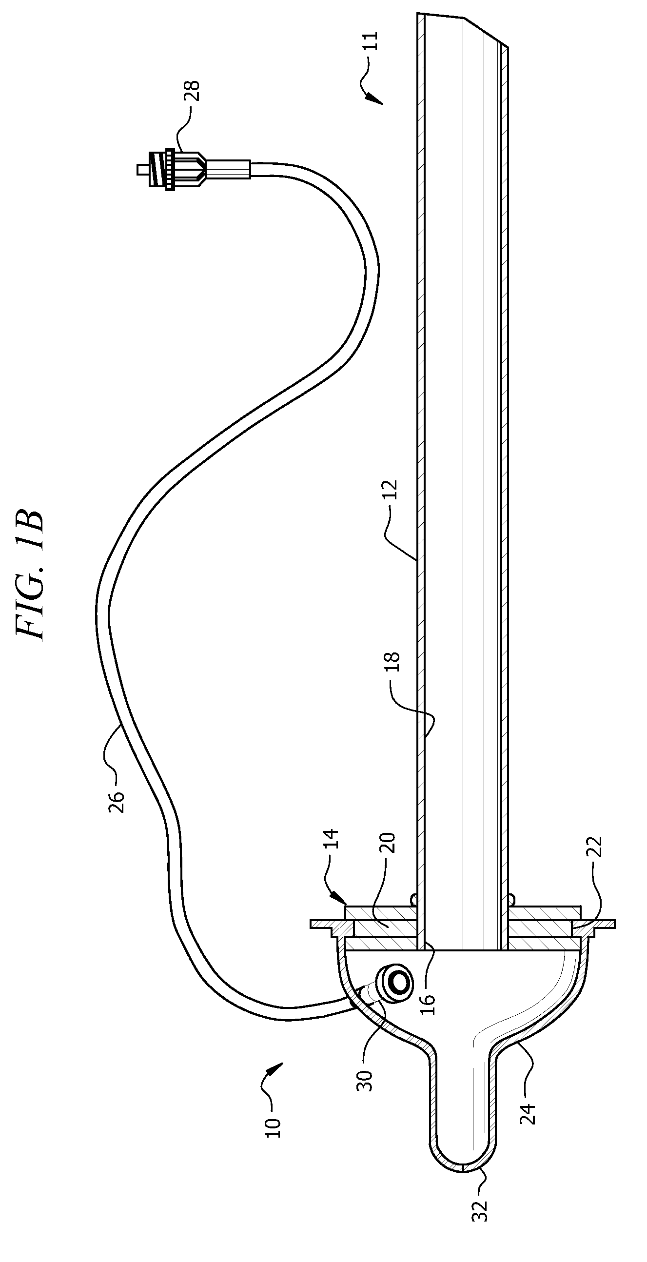
[0044]In this first embodiment, valve 32 is formed in the narrow proximal end or tip of nipple 24. Various preselected surgical instruments may be introduced into the lumen of cannula 10 through said valve. The valve seals around the periphery of the preselected surgical instrument to inhibit leakage of gas and said valve seals the nipple against gas leakage when a surgical instrument is withdrawn from said cannula and attached nipple because the material of which nipple 24 is made is resilient.

[0045]Valve 32 may be provided in the form of a duckbill valve as well, or in the form of a cross-slit valve. Examples of such valves may be seen at minivalve.com.

[0046]Nipple 24 is mass produced at a very low cost for use on baby bottles and thus its use in this environment represents a substantial cost savings over conventional means for interconnecting a gas machine to a cannula.

second embodiment

[0047]The second embodiment is depicted in FIGS. 3A and 3B. Baby bottle nipple 24 is used in this embodiment but the narrow leading end of the nipple is cut off at its base to create a circular opening. A valve means such as cross-slit valve 40, a duckbill valve, or other suitable valve means is seated in said opening as depicted in FIG. 3A but perhaps better understood in connection with FIG. 3B.

[0048]This second embodiment works in the same way as the first embodiment but the use of valve means 40 may enhance the seal around a surgical instrument inserted into lumen 18 of cannula main body 12.

[0049]However, forming a cut or cuts such as slits 32 in the narrow proximal end of nipple 24 to form a leak-proof valve as in the first embodiment may be more cost-effective than cutting off said narrow proximal end at its base and installing a pre-manufactured valve.

[0050]A third embodiment is depicted in FIGS. 4-6. It can be used with the first or second embodiments but works best with the...


PUM


Abstract

A cannula for delivering gas to an abdominal cavity includes a tubular main body that defines a lumen. A hub is formed at the proximal end of the main body and a central bore is formed in the hub. An annular groove is formed in an outer periphery of the hub. A nipple has a radially-inwardly extending annular ridge formed in it and the diameter of the annular ridge is slightly less than a diameter of the annular groove so that the annular groove releasably but snugly receives the annular ridge. An elongate hose is adapted to provide fluid communication between a remote gas machine and an enclosed space defined by the nipple and the hub when the nipple is attached to the hub. Gas under pressure is delivered to an abdominal cavity of a patient through the hose, the enclosed space, and the lumen.

Description

CROSS REFERENCE TO RELATED APPLICATIONS[0001]This application is a continuation-in-part of co-pending U.S. patent application Ser. No. 12 / 132,395, filed Jun. 3, 2008, which is a continuation-in-part of co-pending U.S. patent application Ser. No. 11 / 935,813, filed Nov. 6, 2007, both of which have the same inventor and both of which are entitled “Adaptor for Connecting Cannula to Gas Machine.”BACKGROUND OF THE INVENTION[0002]1. Field of the Invention[0003]This invention relates, generally, to surgical tools. More particularly, it relates to an adaptor for cannulas used in laparoscopic surgery.[0004]2. Description of the Prior Art[0005]The size of an incision is minimized in laparoscopic surgery so that post-operative recovery is faster and less painful than conventional large incision surgery. A trocar is a tube-like tool that is inserted into a small incision; it can be left in position so that its lumen provides a passageway for other surgical tools that are used in the course of a ...

Claims


Application Information

Patent Timeline
Patent Type & Authority Patents(United States)
IPC IPC(8): A61M37/00
CPCA61B17/3474A61M13/003A61B17/3421
Inventor TEVES, LEONIDES Y.
Owner TEVES LEONIDES Y
Why Eureka
Try Eureka