Mechanical arm end executor

A technology of end effectors and robotic arms, applied in the field of end effectors of robotic arms, which can solve the problems of inability to perform simultaneous rotation, grasping and positioning of circular workpieces, etc., and achieve the effect of reducing production costs

Active Publication Date: 2019-01-25
BEIJING MECHANICAL EQUIP INST
View PDF8 Cites 7 Cited by
  • Summary
  • Abstract
  • Description
  • Claims
  • Application Information

AI Technical Summary

Problems solved by technology

[0005] In view of the above analysis, the present invention aims to provide a mechanical arm end effector to solve the problem that the existing end effector cannot realize the accurate grasping and positioning of the round workpiece, and cannot perform simultaneous rotation

Method used


Image

  • Mechanical arm end executor

Examples


Embodiment Construction

[0030] Preferred embodiments of the present invention will be described in detail below in conjunction with the accompanying drawings, wherein the accompanying drawings constitute a part of the application and together with the embodiments of the present invention are used to explain the principle of the present invention and are not intended to limit the scope of the present invention.

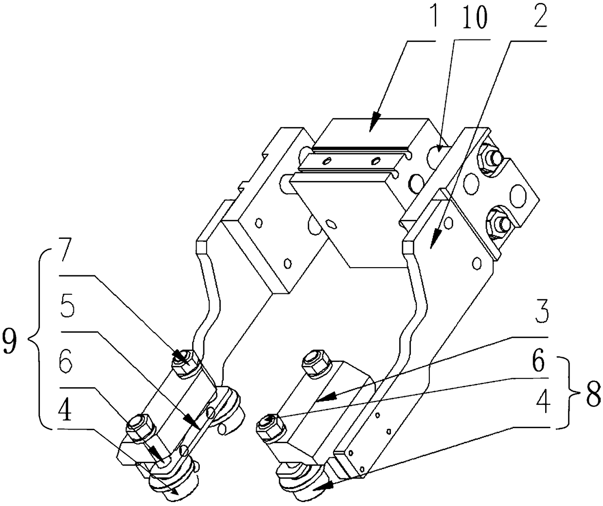
[0031] A specific embodiment of the present invention discloses a mechanical arm end effector, such as figure 1 As shown, it includes the air gripper 1 and the air gripper connecting plate 2 arranged on both sides of the air gripper 1. The end of the air gripper connecting plate 2 is provided with a roller structure 9, and the roller structure 9 is arranged symmetrically with respect to the air gripper 1; the roller structure 9 includes a roller bracket 3 and two roller assemblies 8, and the two roller assemblies 8 are arranged side by side on the roller bracket 3, and the roller assemblies 8 ...


PUM


Abstract

The invention relates to a mechanical arm end executor, and belongs to the technical field of industrial automation. The problems are solved that existing end executors cannot accurately grasp and position circular workpieces or simultaneously rotate the circular workpieces. The mechanical arm end executor comprises a gas claw and gas claw connecting plates arranged at the two sides of the gas claw; the end portions of the gas claw connecting plates are provided with rolling wheel structures, and the rolling wheel structures are symmetrically arranged about the gas claw; each rolling wheel structure comprises a rolling wheel bracket and two rolling wheel assemblies, and the rolling wheel assemblies are arranged on each rolling wheel bracket in parallel, and used for clamping the circular workpieces and conducting centering positioning on the circular workpieces. Each rolling wheel assembly comprises a rolling wheel and a connecting rod, each rolling wheel is fixedly connected to the end portion of the corresponding connecting rod, and the connecting rods can rotate in bracket through holes and move up and down. The mechanical arm end executor is low in cost and can accurately graspthe circular workpieces and cooperate with other equipment to make the circular workpieces rotate.

Description

technical field [0001] The invention relates to the technical field of industrial automation, in particular to a mechanical arm end effector. Background technique [0002] In the field of industrial automation, the end effector of the robotic arm is a tool that is connected to the end joint of the robotic arm and has certain functions. The application of the end effector of the robotic arm as a loading and unloading gripper is the most common. According to the needs of the operation, the end effector can have different structural forms and connection methods. It can be used as a loading and unloading gripper to grasp the workpiece, it can be used as an electric welding torch to realize the automatic welding process, and it can also be used as a collision sensor to realize stress detection and so on. [0003] When the end effector is used as a loading and unloading gripper, it is usually divided into two types in form, air suction type and clamping type. Among them, the air s...

Claims


Application Information

Patent Timeline
Patent Type & Authority Applications(China)
IPC IPC(8): B25J15/00B25J15/02B25J15/08
CPCB25J15/0028B25J15/0253B25J15/08
Inventor 李也然佈仁吉日嘎李大伟李晓光李雪初耿铭
Owner BEIJING MECHANICAL EQUIP INST
Why Eureka
Try Eureka