Cement stirring machine and feeding and discharging method thereof

A cement mixer, feeding and discharging technology, applied in cement mixing devices, chemical instruments and methods, unloading devices, etc., can solve the problems of inconvenient insertion and removal of test materials, inability to test cement concrete, and incomplete mixing, etc. Save the cost of test equipment, avoid efficiency and safety problems, and achieve complete discharge

Pending Publication Date: 2019-01-25
CHANGAN UNIV
View PDF7 Cites 3 Cited by
  • Summary
  • Abstract
  • Description
  • Claims
  • Application Information

AI Technical Summary

Problems solved by technology

[0002] The cement paste mixer is a special instrument and equipment used in the laboratory for testing the physical properties of cement. The stirring shaft on the cement paste mixer of the prior art is fixed inside the equipment and cannot be removed. Due to the limited laboratory conditions, the mixing The container is semi-fixed on the stirring frame, and the stirring container cannot rotate by itself, but the stirring shaft rotates for stirring, because there is a gap between the stirring shaft and the inner wall of the stirring container, which leads to uneven stirring and incomplete stirring; because the stirring shaft extends into the stirring container , and the mixing blades set on it together block the inlet and outlet to a certain extent, which makes it inconvenient to put in and take out the test material. The test material can only be poured out by the experimenter manually, which is also dangerous. And it can only be tested on cement paste, but not on cement concrete, and the purpose is single

Method used


Image

  • Cement stirring machine and feeding and discharging method thereof
  • Cement stirring machine and feeding and discharging method thereof
  • Cement stirring machine and feeding and discharging method thereof

Examples


Embodiment Construction

[0035] The present invention is described in further detail below in conjunction with accompanying drawing:

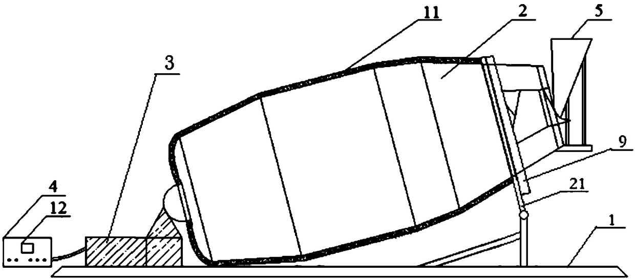
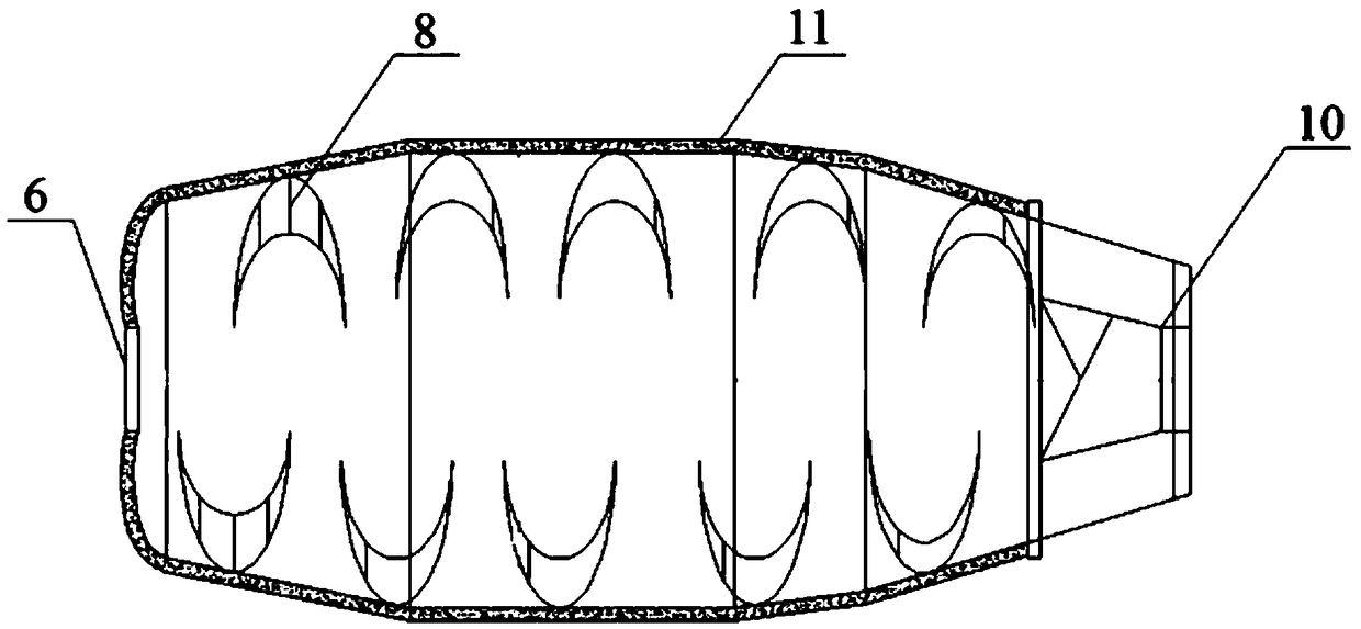
[0036] Such as figure 1 As shown, the present invention is a special instrument and equipment for cement physical performance inspection, which is composed of a stirring frame 1, a stirring container 2, a hydraulic transmission device 3, a control device 4, a feeding device 5, a driving device 9 and a support frame 21; the support frame 21 Fixed on the stirring frame 1, located near the front end of the stirring container 2, used to support the front end of the stirring container 2 to a certain height; the hydraulic transmission device 3 is fixed on the stirring frame 1, located at the rear end of the stirring container 2; the stirring container 2 is fixed On the support frame 21, the interior of the stirring container 2 is hollow, and the front end face is provided with an inlet and outlet 10; the feeding device 5 is hinged and fixed on the stirring container 2 throug...


PUM

PropertyMeasurementUnit
diameteraaaaaaaaaa
volumeaaaaaaaaaa

Abstract

The invention discloses a cement stirring machine and a feeding and discharging method thereof. The cement stirring machine comprises a stirring frame, a stirring container, a hydraulic transmission device, a control device and a driving device, wherein the inside of the stirring container is hollow, a feeding and discharging opening is arranged at an end face of the front side of the stirring container, a supporting frame is arranged on the stirring frame to supporting the peripheral surface of the stirring container, the center of an end face of the rear end of the stirring container is in hinge connection with the hydraulic transmission device, a stirring blade is arranged on an inner wall of the stirring container, the hydraulic transmission device can drive the rear end of the stirring container to move in the vertical direction, the driving device is used for providing power for the stirring container to rotate around the axis of the stirring container, and the control device isused for controlling startup, shutdown and the rotating direction of the driving device. By means of the cement stirring machine, experimental materials can be put into and taken out conveniently, thestirred materials can reach a fully even degree, and a cement test accuracy degree is improved.

Description

technical field [0001] The invention belongs to the field of experimental instruments, and relates to a cement mixer and a material feeding and discharging method thereof. Background technique [0002] The cement paste mixer is a special instrument and equipment used in the laboratory for testing the physical properties of cement. The stirring shaft on the cement paste mixer of the prior art is fixed inside the equipment and cannot be removed. Due to the limited laboratory conditions, the mixing The container is semi-fixed on the stirring frame, and the stirring container cannot rotate by itself, but the stirring shaft rotates for stirring, because there is a gap between the stirring shaft and the inner wall of the stirring container, which leads to uneven stirring and incomplete stirring; because the stirring shaft extends into the stirring container , and the mixing blades set on it together block the inlet and outlet to a certain extent, which makes it inconvenient to put...

Claims


Application Information

Patent Timeline
Patent Type & Authority Applications(China)
IPC IPC(8): B28C5/18B28C7/16
CPCB28C5/1806B28C5/1856B28C5/1862B28C5/1875B28C7/16
Inventor 申爱琴王文真郭寅川李得胜王建文
Owner CHANGAN UNIV
Why Eureka
Try Eureka