Temperature control system

a control system and temperature technology, applied in the field of temperature control systems, can solve the problems of inconvenient window of time, medical complications, and delay in the completion of the procedure, and achieve the effect of reducing the risk of premature setting and increasing safety

Active Publication Date: 2018-03-20
DEPUY SYNTHES PROD INC
View PDF976 Cites 9 Cited by
  • Summary
  • Abstract
  • Description
  • Claims
  • Application Information

AI Technical Summary

Benefits of technology

[0014]A broad aspect of some embodiments of the invention relates to retarding setting kinetics of self-setting bone filler materials after components thereof are mixed. In an exemplary embodiment of the invention, retarding of setting kinetics is carried out in a sterile environment. Optionally, retarding of setting kinetics increases safety by reducing a risk of premature setting. “Setting” as used in this specification and the accompanying claims refers to hardening. A bone filler material is deemed “set” when it has hardened to a point where it cannot be used with an available delivery system.
[0034](b) control circuitry adapted to output a control signal to the cooling mechanism so that the mixture does not set before a minimum setting time.
[0053]In an exemplary embodiment of the invention, there is provided a method of increasing a setting time of a bone cement, the method comprising:

Problems solved by technology

Setting of the material prior to completion of the procedure can delay completion of the procedure and / or cause medical complications.
A window of time which is too small can be inconvenient, for example if a long procedure is planned (e.g. treatment of two or more vertebrae in a single operation) and / or if an unplanned delay occurs.
Cooling of components of the polymerization reaction mixture prior to mixing can delay polymerization to a limited extent, however the delay is uncontrollable once mixing begins and the amount of delay cannot be accurately predicted.
Additionally, since polymerization reactions are typically exothermic, any advantage offered by cooling mixture components prior to mixing is typically lost once the polymerization reaction begins to generate heat.

Method used


Image

  • Temperature control system
  • Temperature control system
  • Temperature control system

Examples


Embodiment Construction

Overview

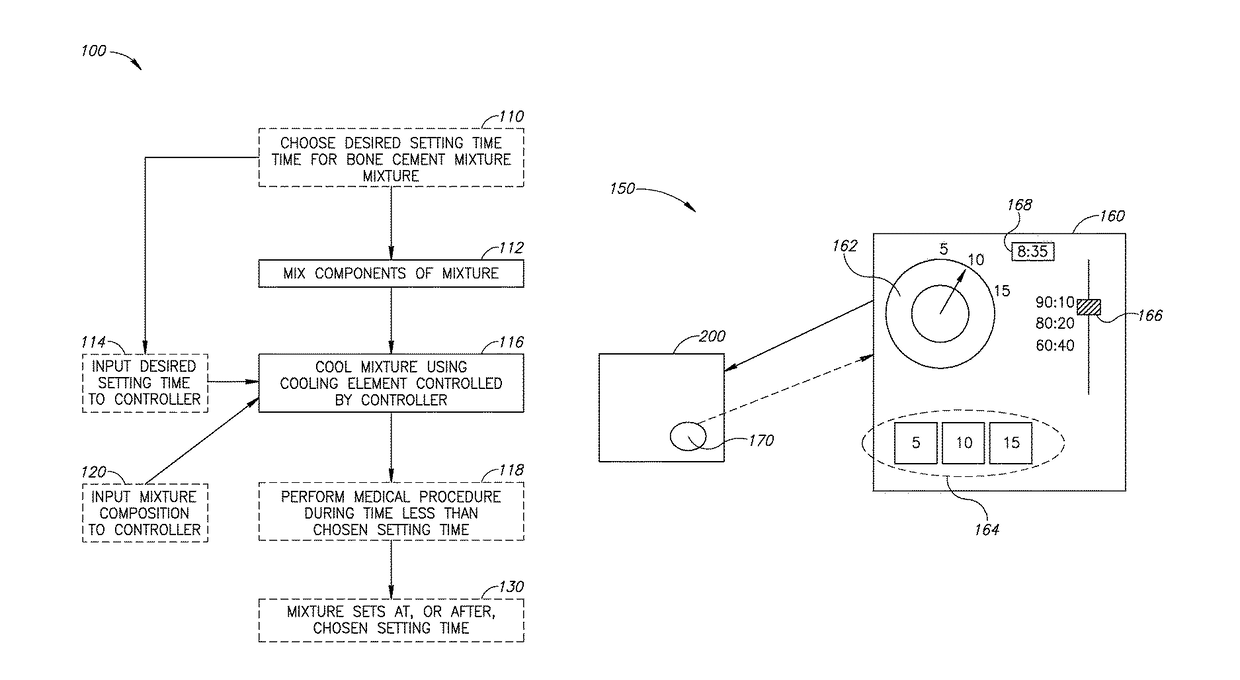
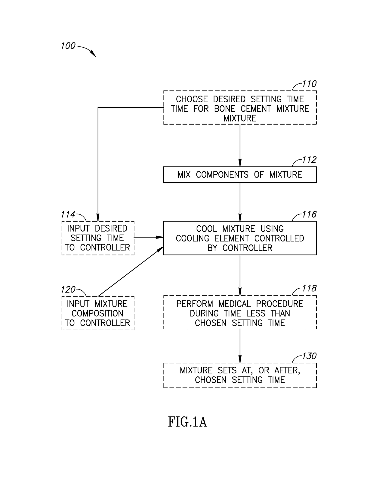
[0078]FIG. 1A illustrates an exemplary method 100 according to an exemplary embodiment of the invention.

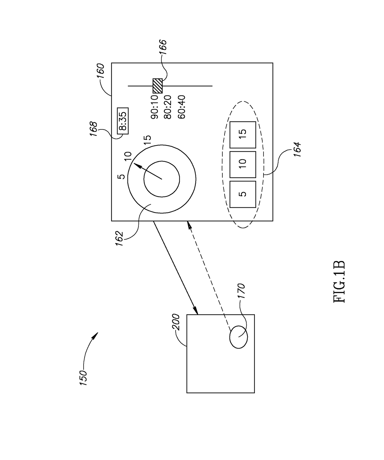
[0079]FIG. 1B schematically depicts an exemplary setting time control system 150 for a reaction mixture according to an exemplary embodiment of the invention.

[0080]During use, bone filler material components are typically mixed in an operating theater and used shortly after mixing is complete. In an exemplary embodiment of the invention, a mixing apparatus, cooling system and cement injection system are all provided as sterile objects so that the cement can be mixed and injected in a sterile field established around a site of entry into the body.

[0081]Referring now to FIGS. 1A and 1B, at 110 a desired setting time for a bone filler material mixture is optionally chosen. The desired setting time can be chosen 110 in consideration of a particular medical procedure being contemplated. In those embodiments of the invention in which the time is chosen in consideration of a part...


PUM


Abstract

A method of regulating a setting time of a bone filler material, the method comprising: (a) combining at least two filler material components to form a biocompatible mixture; (b) choosing a setting time for the mixture; and (c) regulating a temperature of the mixture to influence reaction kinetics so that the mixture does not set before the chosen setting time.

Description

RELATED APPLICATIONS[0001]The present application claims the benefit under 35 USC 119(e) of U.S. provisional applications No. 60 / 814,559, filed on Jun. 19, 2006 and entitled “Method and Apparatus for Extending the Working Time of Bone Filler Materials”, No. 60 / 765,484, filed on Feb. 2, 2006 and entitled “Methods, Materials and Apparatus for Treating Bone and Other Tissue”, No. 60 / 762,789, filed on Jan. 26, 2006 and entitled “Methods, Materials and Apparatus for Treating Bone and Other Tissue”, No. 60 / 738,556, filed on Nov. 22, 2005 and entitled “Methods, Materials and Apparatus for Treating Bone and Other Tissue”, the disclosures of all of which are fully incorporated herein by reference.[0002]The present application is a Continuation in Part of U.S. application Ser. No. 11 / 461,072, filed on Jul. 31, 2006 and entitled “Bone Cement and Methods of Use Thereof”, which is a Continuation in Part of U.S. application Ser. No. 11 / 360,251 filed on Feb. 22, 2006 and entitled “Methods, Materia...

Claims


Application Information

Patent Timeline
Patent Type & Authority Patents(United States)
IPC IPC(8): F23N5/00F28F13/18F28F13/12F24F3/14F28F19/00A61B17/88F25B47/00F25D11/02A61F2/46A61K6/884
CPCA61B17/8836A61F2002/4653A61F2002/469A61B2017/883
Inventor GLOBERMAN, ORENBEYAR, MORDECHAY
Owner DEPUY SYNTHES PROD INC
Why Eureka
Try Eureka