Longitudinal cutting slitting machine

A technology of slitting and slitting machine and rotating shaft, which is applied in the direction of sending objects, thin material processing, transportation and packaging, etc. It can solve the problems of inconvenient blade distance, inconvenient installation and disassembly of blades, etc., so as to improve work efficiency, save manpower and material resources, The effect of satisfying the effect of use

Active Publication Date: 2019-01-25
FOSHAN UNIVERSITY
View PDF20 Cites 4 Cited by
  • Summary
  • Abstract
  • Description
  • Claims
  • Application Information

AI Technical Summary

Problems solved by technology

[0004] The object of the present invention is to provide a slitting and slitting machine. The first blade and the second blade are inserted into the annular slot by operating the cylinder, and the gas is respectively injected into the telescopic air bag through the air pump, the shunt pipe and the hose, and the motorized flow The valve controls the air intake of the hose to keep the gas volume in the telescopic air bag consistent, thereby adjusting the distance between the base rings. When the base ring moves, the knife groove disc moves with the movement of the cutter disc, which solves the existing problem The slitting and slitting machine is inconvenient to adjust the distance between the blades and the blades are not easy to install and disassemble.

Method used


Image

  • Longitudinal cutting slitting machine
  • Longitudinal cutting slitting machine
  • Longitudinal cutting slitting machine

Examples


Embodiment Construction

[0033] The following will clearly and completely describe the technical solutions in the embodiments of the present invention with reference to the accompanying drawings in the embodiments of the present invention. Obviously, the described embodiments are only some, not all, embodiments of the present invention. Based on the embodiments of the present invention, all other embodiments obtained by persons of ordinary skill in the art without creative efforts fall within the protection scope of the present invention.

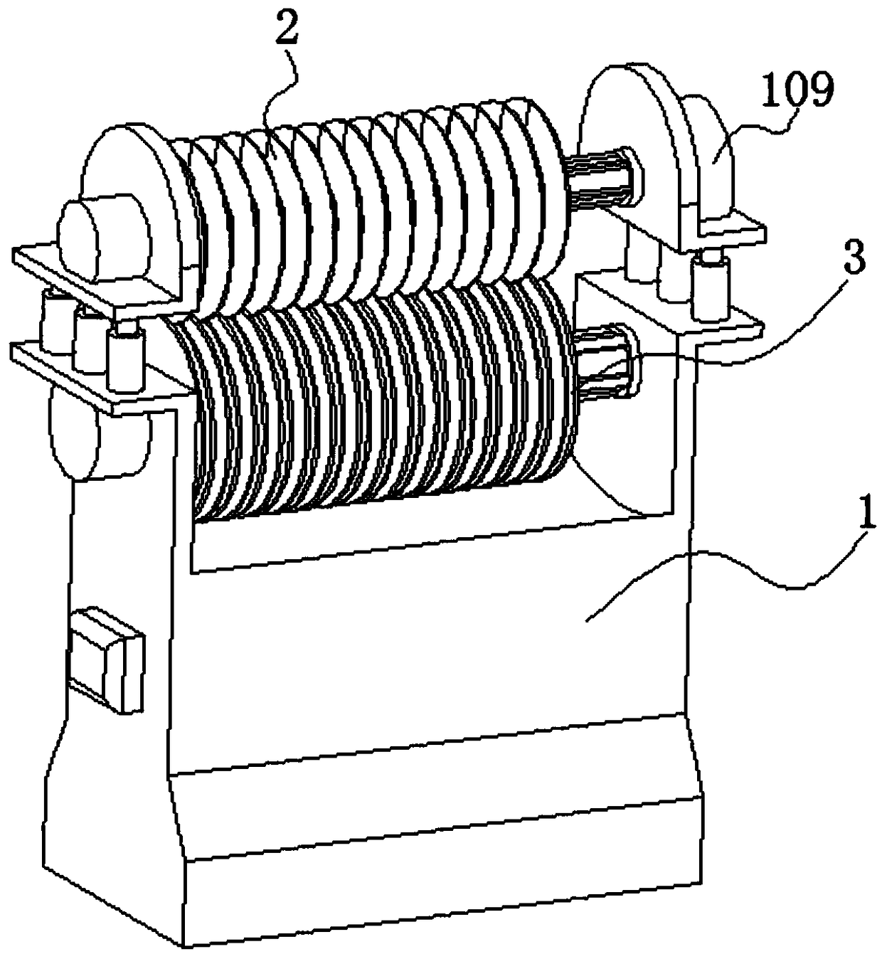
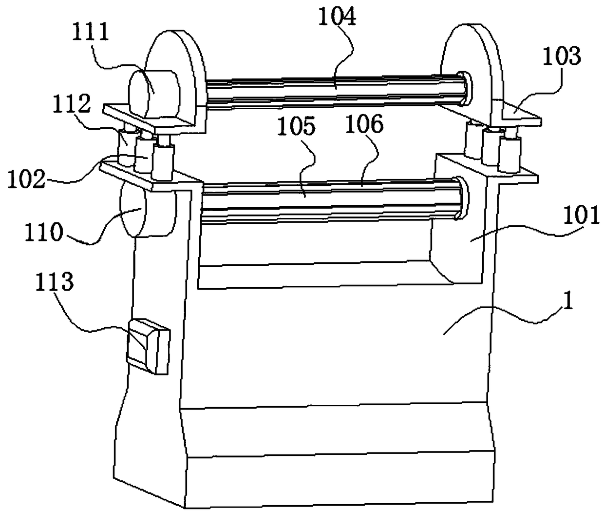
[0034] see Figure 1-9 As shown, the present invention is a slitting and slitting machine, comprising a base 1, a set of first L-shaped plates 101 are fixed on one surface of the base 1, and a second L-shaped plate 101 is fixed on one surface of the first L-shaped plate 101 through a cylinder 102. Shaped plate 103, between two first L-shaped plates 101 is rotatably connected with a first rotating shaft 104, between two second L-shaped plates 103 is rotatably connec...


PUM


Abstract

The invention discloses a longitudinal cutting slitting machine and relates to the technical field of longitudinal cutting slitting machines. The machine includes a base, a group of first L-shaped plates are fixed to one surface of the base, a second L-shaped plate is fixed to one surface of each first L-shaped plate through an air cylinder, a first rotating shaft is rotatably connected between the two first L-shaped plates, and a second rotating shaft is rotatably connected between the two second L-shaped plates; five guiding strips are fixed to the circumferential side faces of the first andsecond rotating shafts. First blades and second blades are inserted into annular groove openings through running of the air cylinder, and gas is introduced into a retractable gasbag by separately utilizing an air pump, a diversion pipe and hoses; the gas feeding amount of the hoses is controlled through an electric flow valve to maintain the amount of the gas in the retractable gasbag uniform, and therefore the distance between base rings is adjusted; when the base rings move, a cutter groove disc moves along with the movement of a cutter disc, and the problems that the distance among bladesis inconvenient to adjust by existing longitudinal cutting slitting machines and the blades are inconvenient to install and dismantle are solved.

Description

technical field [0001] The invention belongs to the technical field of slitting and slitting machines, in particular to a slitting and slitting machine. Background technique [0002] The slitting and slitting machine is composed of upper and lower cutter shafts, fixed archway, movable archway and synchronous lifting structure. The archway is cast, aged, and precision-machined by a boring machine. Made of fine craftsmanship. [0003] The traditional slitting and slitting machine is inconvenient to adjust the distance between the two cutters, excessive waste of manpower and material resources, thereby reducing the working efficiency of the slitting machine, and the existing cutting knives on the slitting and slitting machine are not easy to install and Disassembly is not convenient for the user to use, and cannot satisfy the user's use effect. Contents of the invention [0004] The object of the present invention is to provide a slitting and slitting machine. The first bla...

Claims


Application Information

Patent Timeline
Patent Type & Authority Applications(China)
IPC IPC(8): B65H35/02
CPCB65H35/008B65H35/02B65H2301/515326Y02E60/10
Inventor 李丽芬
Owner FOSHAN UNIVERSITY
Why Eureka
Try Eureka