E-shaped inductance automatic processing device

An automatic processing and inductance technology, applied in the manufacture of inductance/transformer/magnet, circuits, electrical components, etc., can solve problems such as uneven shape, uneven bending of wires, manual straightening, etc., to achieve high linkage and improve product quality , to achieve the effect of continuity

Active Publication Date: 2019-01-25
阜阳汇中芯自动化技术有限公司
View PDF7 Cites 8 Cited by
  • Summary
  • Abstract
  • Description
  • Claims
  • Application Information

AI Technical Summary

Problems solved by technology

[0005] The purpose of the present invention is to address the deficiencies of the prior art, by setting the clamping mechanism to cooperate with the adjustment mechanism to realize the automatic loading of the wires and the clamping of the wires, and then cooperate with the smoothing mechanism to unfold and straighten the wires, thereby solving the wiring work When the wire is bent unevenly, the shape is different, and the technical problem that the wire needs to be straightened manually after the wiring is completed

Method used


Image

  • E-shaped inductance automatic processing device
  • E-shaped inductance automatic processing device
  • E-shaped inductance automatic processing device

Examples


Embodiment 1

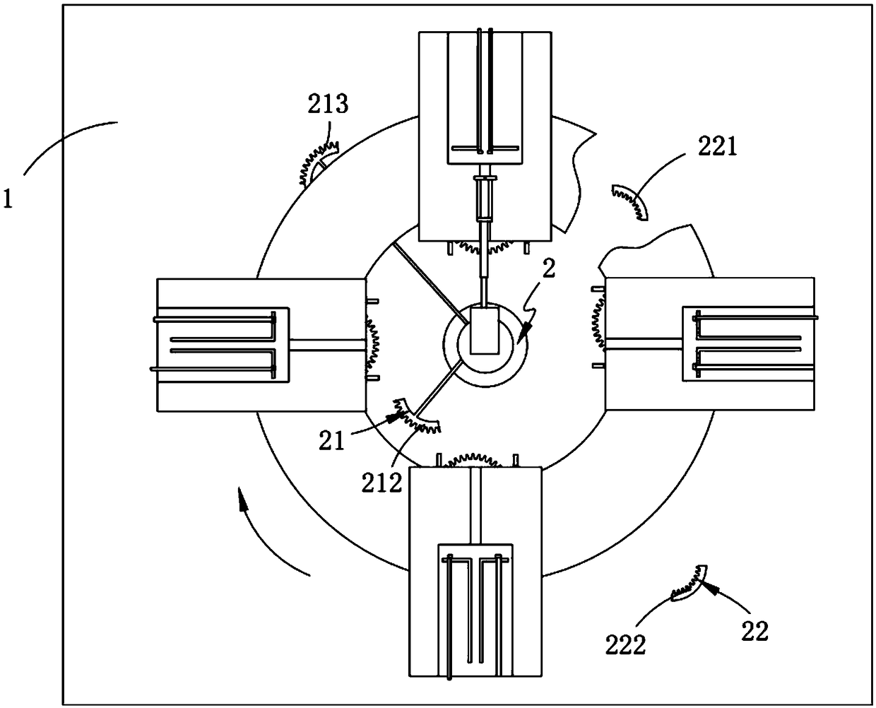
[0078] Such as figure 1 As shown, an E-shaped inductance automatic processing device includes:

[0079] Rack 1;

[0080] An adjustment mechanism 2, the adjustment mechanism 2 is fixedly arranged on the frame 1;

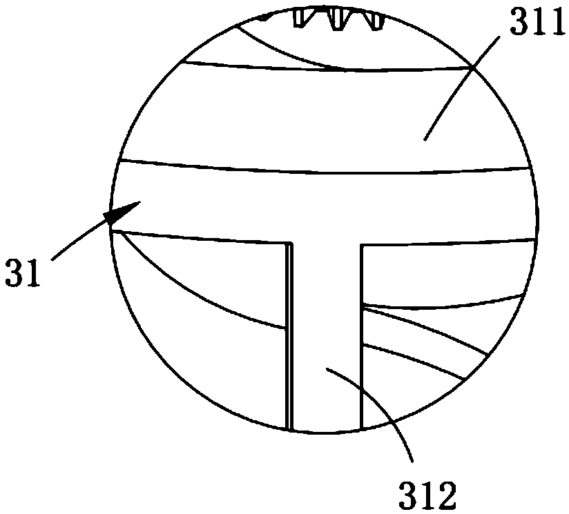
[0081] Clamping mechanism 3, the clamping mechanism 3 includes a revolving assembly 31, fixedly arranged on the revolving assembly 31 and four sets of feeding assemblies 32 arranged in a circular array, fixedly arranged at the bottom of the feeding assembly 32 and located at the The first positioning assembly 33 provided at the front end of the feeding assembly 32 and the second positioning assembly 34 located at the rear end of the feeding assembly 32;

[0082] a smoothing mechanism 4, the smoothing mechanism 4 is fixedly arranged on the adjustment mechanism 2 and cooperates with the second positioning assembly 34 for transmission; and

[0083] The coil delivery mechanism 5, the coil delivery mechanism 5 includes a crimping machine 51 arranged at the output end of...

Embodiment 2

[0135] Such as Figure 8 As shown, the components that are the same as or corresponding to those in the first embodiment are marked with the corresponding reference numerals in the first embodiment. For the sake of simplicity, only the differences from the first embodiment will be described below. The difference between this embodiment two and embodiment one is:

[0136] Going a step further, as in Figure 12 As shown, the discharge assembly 53 includes:

[0137] A limiting plate 531, the limiting plate 531 is located at the output end of the uploading assembly 52 and is rotatably arranged on the uploading assembly 52, the limiting plate 531 is provided with a control slot 532, and the control slot 532 is connected to the uploading assembly 52. Said sliding part 522 matching setting;

[0138] The mounting frame 533, the mounting frame 533 is fixedly arranged on the frame platform 5211 and arranged linearly with the rotating shaft 535 of the limiting plate 531;

[0139] A s...


PUM


Abstract

The invention relates to an E-shaped inductance automatic processing device, comprising a frame; An adjusting mechanism fixedly arranged on the rack; A clamping mechanism comprising a turnover assembly fixedly arranged on the turnover assembly and provided with four groups of feeding assemblies in a circumferential array, a first positioning assembly fixedly arranged at the bottom of the feeding assembly and positioned at the front end of the feeding assembly, and a second positioning assembly fixedly arranged at the rear end of the feeding assembly; A smoothing mechanism fixedly arranged on the tightening assembly and cooperated with the second positioning assembly to drive; And a coil conveying mechanism, wherein the coil conveying mechanism comprises a wire pressing machine arranged atthe output end of the smoothing mechanism, an uplink assembly arranged at one side of the wire pressing machine and perpendicular to the output end of the smoothing mechanism, and a discharge assemblyarranged at the output end of the transmission assembly; The invention solves the technical problems that the wires are uneven in bending and different in shape when the wires are connected, and thewires still need to be manually straightened after the wires are connected.

Description

technical field [0001] The invention relates to the technical field of inductance coil materials, in particular to an E-shaped inductance automatic processing device. Background technique [0002] With the rapid development of economy and technology, inductors play an increasingly important role in our lives and are one of the indispensable components in many electronic systems. Inductor-based transformers also play an important role in many fields. Regardless of inductors or transformers, wires are usually wound into coils, and an iron core is used to press down the wires and coils into one. [0003] The patent document whose patent number is CN207818329U discloses an inductance coil, which includes a coil housing, wires and pins. Groove and heat conduction material, the groove is provided on the surface of the coil housing, the groove contains heat conduction material, and the surface of the wire is provided with heat dissipation material. [0004] However, in the actual...

Claims


Application Information

Patent Timeline
Patent Type & Authority Applications(China)
IPC IPC(8): H01F41/082
CPCH01F41/082
Inventor 沈国栋
Owner 阜阳汇中芯自动化技术有限公司
Why Eureka
Try Eureka