
A kind of rapid assembly equipment for power distribution cabinet

A technology for assembling equipment and power distribution cabinets, which is applied in the field of rapid assembly equipment for power distribution cabinets, can solve the problems of connecting power supplies and electrode plates, and achieve the effects of ingenious structure, quick and convenient installation, and good molding effects

Active Publication Date: 2020-04-07
山东泰开送变电有限公司
View PDF7 Cites 0 Cited by
  • Summary
  • Abstract
  • Description
  • Claims
  • Application Information

AI Technical Summary

Problems solved by technology

[0005] The purpose of the present invention is to address the deficiencies of the prior art, by setting the mold component of the zero line bending mechanism and the control component to synchronously and reversely press the zero line to form, and fasten it on the power supply and the integrated board, thereby solving the problem of dispensing. When the power supply inside the electric cabinet is connected to the electrode plate with a neutral wire, it is necessary to manually twist the neutral wire into a suitable shape before connecting it to the power supply and the electrode plate.

Method used


Image

  • A kind of rapid assembly equipment for power distribution cabinet
  • A kind of rapid assembly equipment for power distribution cabinet
  • A kind of rapid assembly equipment for power distribution cabinet

Examples


Embodiment 1

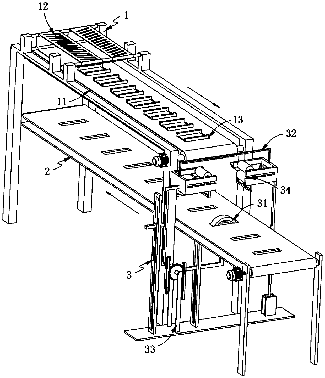
[0078] Such as figure 1 , Figure 11 As shown, a rapid assembly equipment for power distribution cabinets, including:

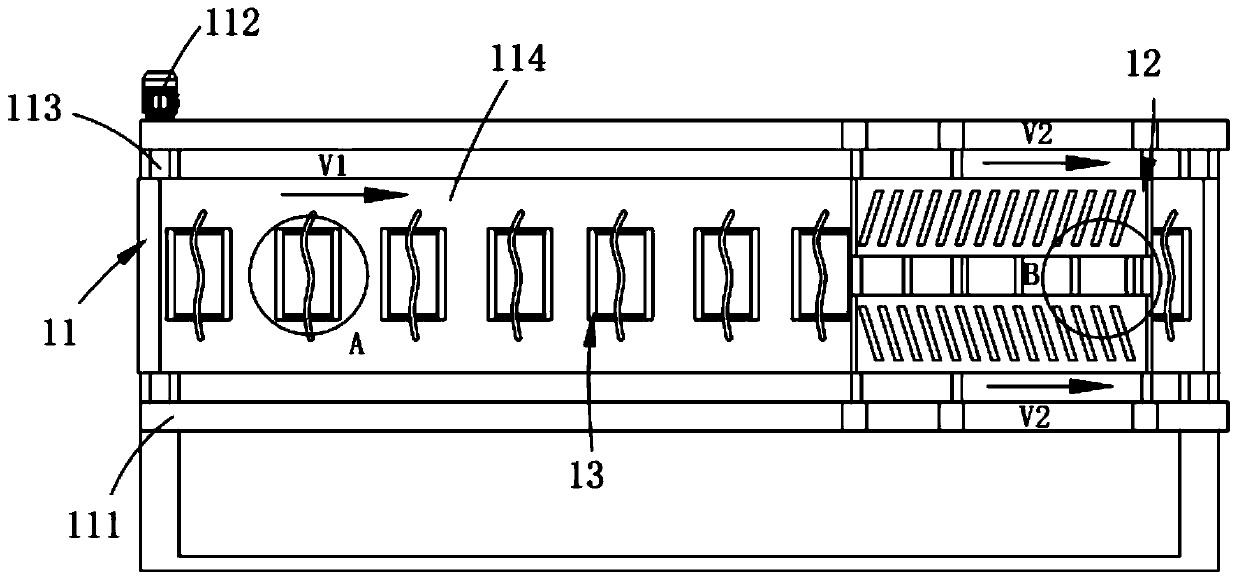
[0079] The zero-line loading mechanism 1, the zero-line loading mechanism 1 includes a forward conveying member 11, two groups of rollers arranged above the forward conveying member 11 and arranged symmetrically along the centerline of the width of the forward conveying member 11 The pressing member 12 and several groups of straightening members 13 are equidistantly arranged along the forward conveying member 11;

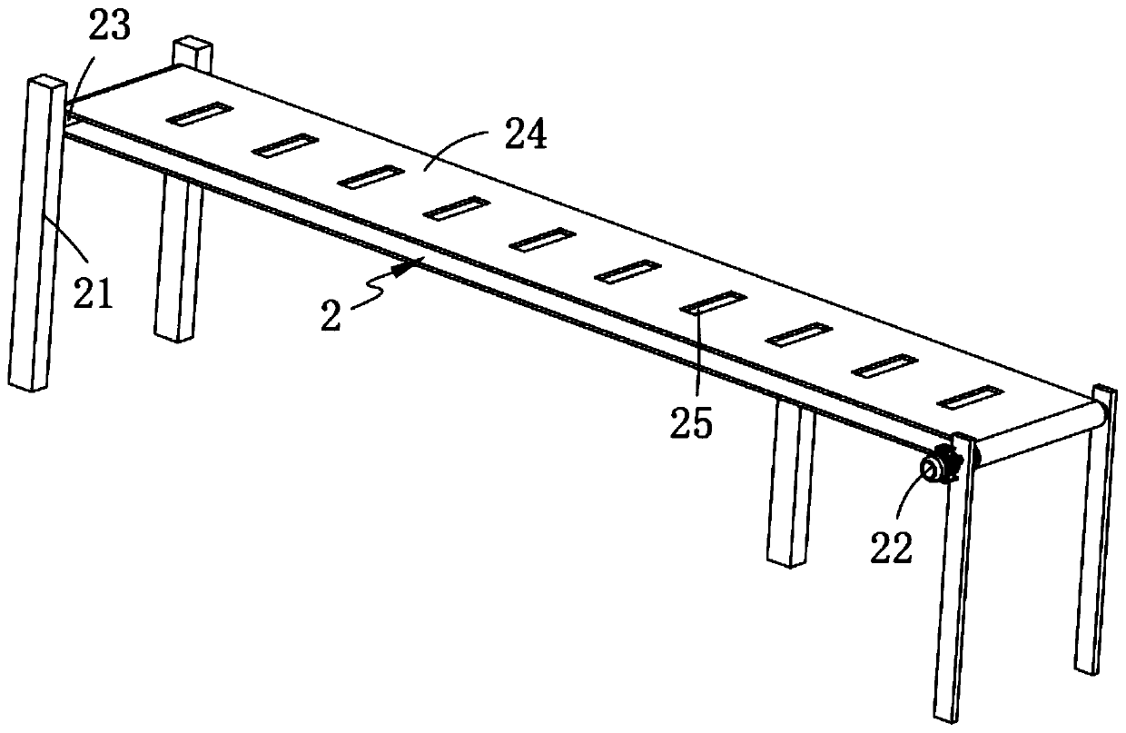
[0080] An electrode plate loading mechanism 2, the electrode plate loading mechanism 2 is set opposite to the conveying direction of the forward conveying member 11 and is located directly below the forward conveying member 11; and

[0081] A zero-line bending mechanism 3, the zero-line bending mechanism 3 includes a mold assembly 31 installed below the pole plate loading mechanism 2, located above the pole plate loading mechanism 2 and cooperati...

Embodiment 2

[0135] Such as Figure 9 As shown, the components that are the same as or corresponding to those in the first embodiment are marked with the corresponding reference numerals in the first embodiment. For the sake of simplicity, only the differences from the first embodiment will be described below. The difference between this embodiment two and embodiment one is:

[0136] further, such as Figure 9 As shown, the boxer assembly 34 includes:

[0137] A support rod 341, one end of the support rod 341 is fixedly connected to the rotation shaft a3262 and the other end is rotatably connected to the rotation shaft b3265;

[0138] The driving rod a342, the upper end of the driving rod a342 is fixedly arranged on the side wall of the roller a3263;

[0139] A waist groove 343, the waist groove 343 is opened at the lower end of the driving rod a342; and

[0140] The driving rod b344, one end of the driving rod b344 is fixedly arranged on the roller b3266 and the other end is slidably ...


PUM


Abstract

The invention relates to rapid assembling equipment for a power distribution cabinet. The equipment comprises a zero-line loading mechanism, a polar plate assembling mechanism and a zero line bendingmechanism; wherein the zero-line loading mechanism comprises a forward conveying part, two sets of rolling pieces are symmetrically arranged above the forward conveying piece and are symmetrically arranged along the center line of the width of the forward conveying piece, a plurality of sets of straightening pieces are arranged at equal intervals along the forward conveying piece, and the polar plate assembling mechanism is arranged opposite to the conveying direction of the forward conveying part and is positioned right below the forward conveying part; and the zero line bending mechanism comprises a mold assembly and a control assembly, wherein the mold assembly is arranged below the electrode plate assembly mechanism, and the control assembly is arranged above the plate assembly mechanism and is matched with the mold assembly, one end of the transmission assembly is matched with the mold assembly, the other end of the transmission assembly is matched with the control assembly, and the flat angle assembly is arranged on the control assembly. The problem that a power supply in the power distribution cabinet is connected with an electrode plate through a null line is solved, needsto be manually twisted into a proper shape and then is connected to a power supply and an electrode plate.

Description

technical field [0001] The invention relates to the technical field of power distribution cabinet materials, in particular to a rapid assembly device for power distribution cabinets. Background technique [0002] The power distribution cabinet is a fully automatic, multi-functional, intelligent electric energy metering management device for metering, controlling and financial management of electricity consumption. The metering modules of the power distribution cabinet can work independently, so each metering module can also be separated from the power distribution cabinet as a The energy meter is hung on the power grid alone, which can save wiring and reduce space. Each metering module has a 485 interface, hangs on the 485 bus, and then connects to the computer. The computer operates and controls each module. [0003] Patent No. CN207611978U discloses a power distribution cabinet with good moisture-proof and dust-proof performance for outdoor use, including a main body and a...

Claims


Application Information

Patent Timeline
Patent Type & Authority Patents(China)
IPC IPC(8): B23P21/00
Inventor 王子轩刘旭东陈林聪陈建清
Owner 山东泰开送变电有限公司
Learn More