Flash control circuit and mobile terminal

A technology for controlling circuits and flashlights, applied in the field of control, can solve problems such as heating of flashlight control circuits, and achieve the effects of maintaining brightness, high brightness, and reducing current

Active Publication Date: 2019-01-25
SHENZHEN TECNO TECH CO LTD
View PDF6 Cites 1 Cited by
  • Summary
  • Abstract
  • Description
  • Claims
  • Application Information

AI Technical Summary

Problems solved by technology

[0006] The invention provides a flashlight control circuit and a mobile terminal, which are used to solve the problem of serious heating of the flashlight control circuit in the prior art

Method used


Image

  • Flash control circuit and mobile terminal
  • Flash control circuit and mobile terminal

Examples


Embodiment Construction

[0020] The specific implementation manners of the flashlight control circuit and the mobile terminal provided by the present invention will be described in detail below in conjunction with the accompanying drawings.

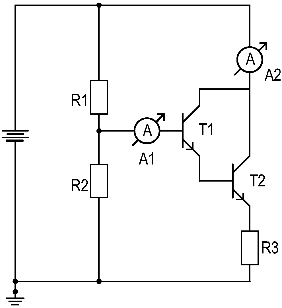
[0021] This specific embodiment provides a flashlight control circuit, with figure 2 It is a structural schematic diagram of the flashlight control circuit in the specific embodiment of the present invention. like figure 2 As shown, the flash lamp control circuit provided in this specific embodiment includes a flash lamp and a current amplifying structure; the current amplifying structure includes a first triode T1 and a second triode T2, and the current of the first triode T1 The output end is connected with the current input end of the second triode T2; the current amplified by the current amplification structure flows into the flash lamp.

[0022] figure 2 The position of the second ammeter A2 is the installation position of the flashlight. In this embod...


PUM


Abstract

The invention relates to the technical field of control, in particular to a flash lamp control circuit and a mobile terminal. The flash lamp control circuit comprises a flash lamp and a current amplification structure; The current amplification structure comprises a first transistor and a second transistor. The current output terminal of the first transistor is connected with the current input terminal of the second transistor. Current amplified by the current amplification structure flows into the flash lamp. The invention solves the problem of serious heat generation of the transistor and reduces the heat generation in the flash lamp control circuit.

Description

technical field [0001] The invention relates to the field of control technology, in particular to a flashlight control circuit and a mobile terminal. Background technique [0002] With the continuous development of science and technology and the continuous improvement of people's living standards, electronic user terminal devices such as mobile phones, tablet computers, notebook computers, and cameras are becoming more and more popular in people's lives. At the same time, with the advancement of digital image processing technology and charge-coupled device (CCD), digital photography technology has reached an unprecedented level. Under such a background, the existing user terminal equipment has a camera function as a basic equipment. On the user terminal with a camera function, in addition to being provided with a lens necessary for taking pictures, a flashlight with a supplementary light function also needs to be provided. [0003] At present, there are mainly two types of...

Claims


Application Information

Patent Timeline
Patent Type & Authority Applications(China)
IPC IPC(8): H05B37/02
CPCH05B47/10
Inventor 徐家林
Owner SHENZHEN TECNO TECH CO LTD
Why Eureka
Try Eureka