Electric planer

An electric planer and limit groove technology, which is used in the manufacture of flat surface processing machines, wood processing appliances, manufacturing tools, etc., can solve the problems of troublesome installation and replacement, time-consuming and laborious, and achieve a convenient and fast installation process. Effect

Inactive Publication Date: 2019-01-29
浙江汉固达网络信息技术有限公司
View PDF0 Cites 0 Cited by
  • Summary
  • Abstract
  • Description
  • Claims
  • Application Information

AI Technical Summary

Problems solved by technology

At present, when replacing and installing the cutter head of the discarded spiral cutter on the market, it needs to be fastened to the cutter body by a single bolt. Due to the large number of cutter heads, the installation and replacement are very troublesome, time-consuming and labor-intensive.

Method used


Image

  • Electric planer
  • Electric planer
  • Electric planer

Examples


Embodiment Construction

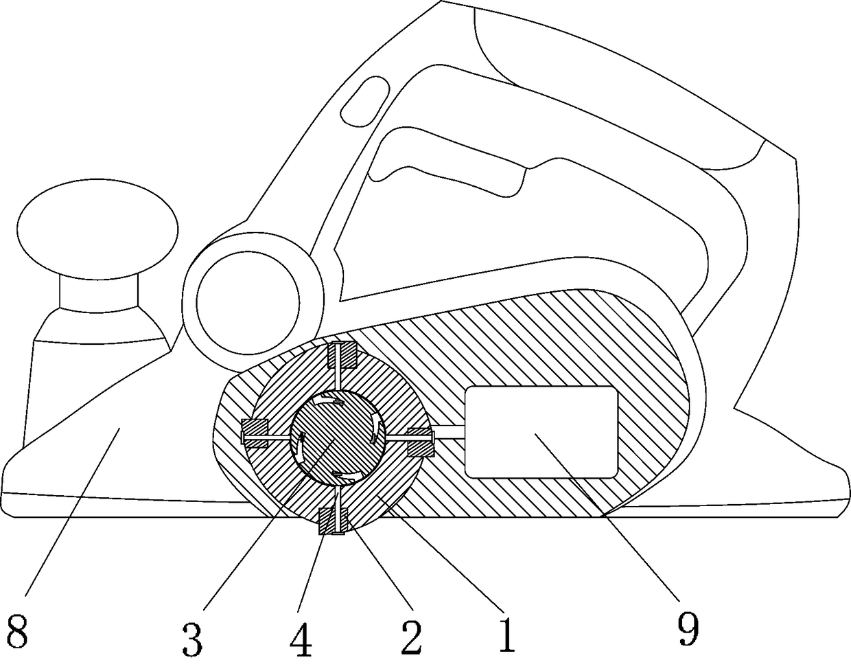
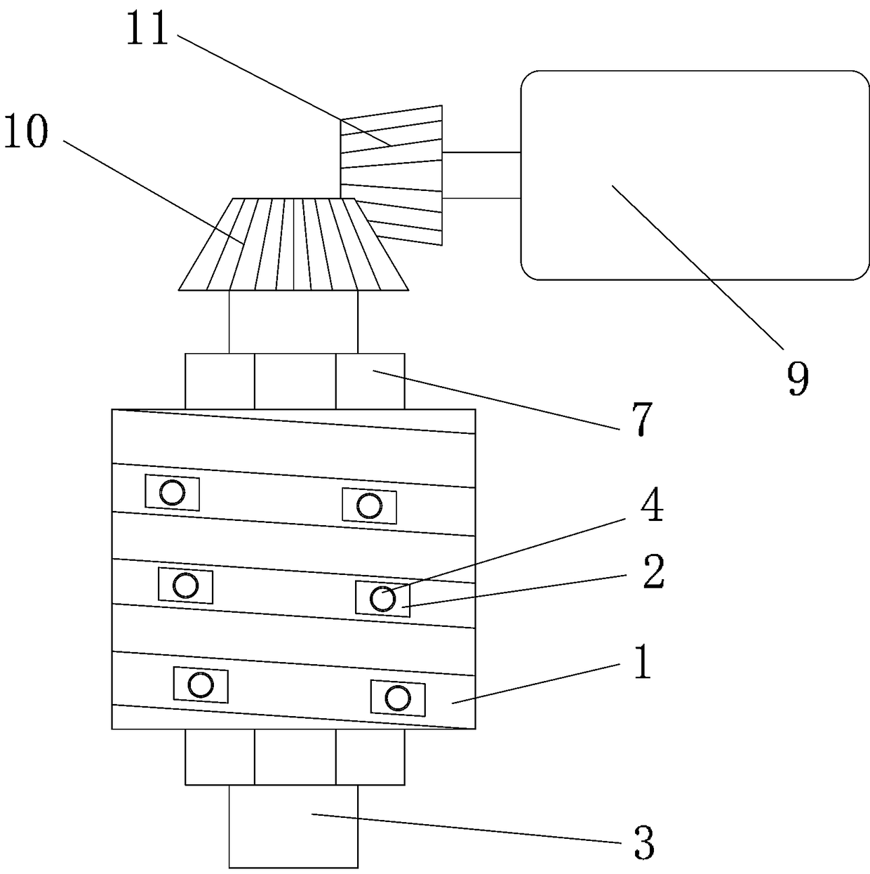
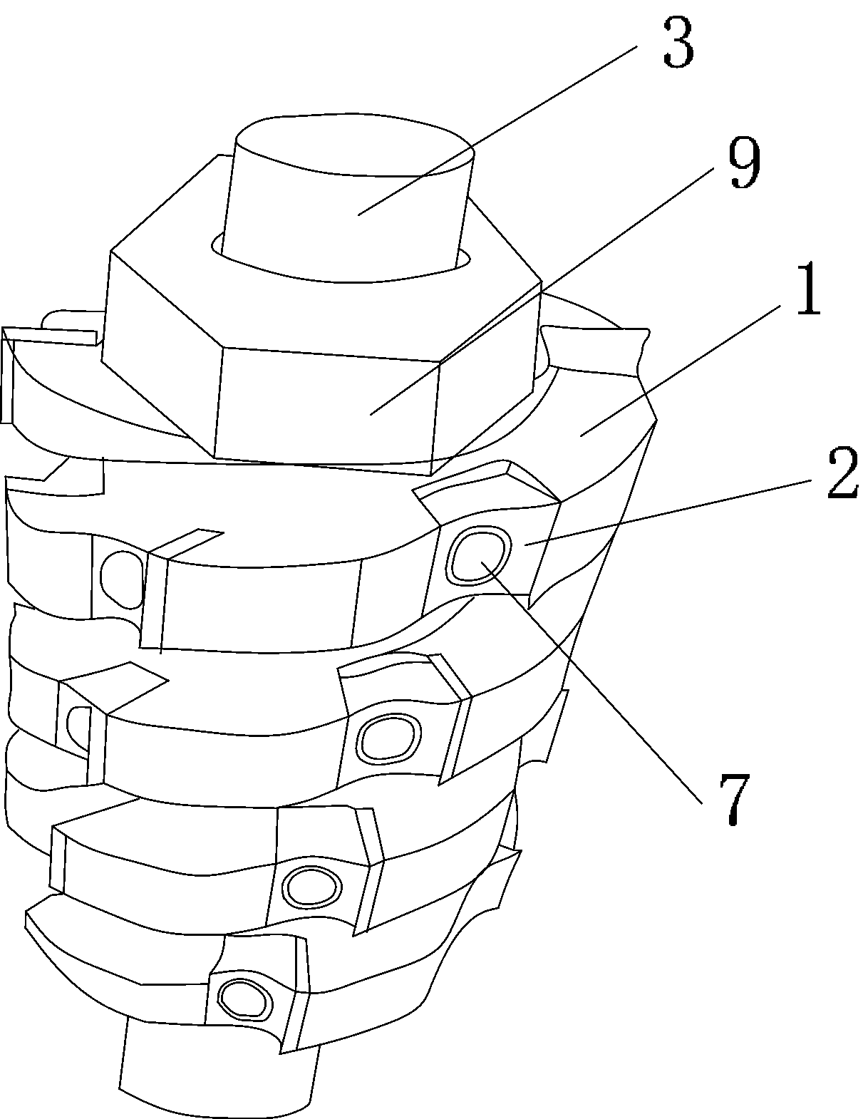
[0023] exist Figure 1-6 Among them, an electric planer includes an electric planer 8, a cutter body 1, a cutter head 2, a rotating shaft 3 and a fixed shaft 4, the rotating shaft 3 is installed in the cutter body 1, and the first connecting shaft is arranged on the rotating shaft 3. Limiting groove 5 and the second limiting groove 6, the number of the first limiting groove 5 and the second limiting groove 6 is 16, the first limiting groove 5 and the second limiting groove 6 spirals are evenly distributed on the rotating shaft 3, and the distance from the notch of the second limiting 6 to the axis of the rotating shaft 3 is greater than the distance from the tail of the second limiting 6 groove to the axis of the rotating shaft 3. The fixed shaft 4 passes through the cutter head 2 and the cutter body 1 and snaps into the first limiting groove 5, and the rotating shaft 3 is rotated to move the fixed shaft 4 from the first limiting groove 5 to the first limiting groove 5. In th...


PUM


Abstract

The invention discloses an electric planer. The electric planer comprises a cutter body, cutter heads, a rotating shaft and fixing shafts; the rotating shaft is installed in the cutter body, first limiting grooves and second limiting grooves which are in communication are formed in the rotating shaft, and the fixing shafts penetrate through the cutter heads and the cutter body to be clamped into the first limiting grooves; the rotating shaft is rotated to move the fixing shafts from the first limiting grooves to the second limiting grooves, and until the two ends of the fixing shafts are abutted against the cutter heads and the second limiting grooves respectively; and a first gear is arranged at one end of the rotating shaft, the first gear is meshed with a motor gear of the motor, and the other end of the rotating shaft is rotationally connected to an electric planer side plate. According to the electric planer, the whole installation process is convenient and fast, multiple cutter heads of the cutter body can be synchronously installed and fixed at one time, so that the working efficiency is greatly improved.

Description

technical field [0001] The invention relates to the technical field of electric tools, in particular to an electric planer. Background technique [0002] Disposable spiral cutter head With the development of science and technology, the discarded spiral cutter head has gradually replaced the traditional flat knife, four-sided planer, etc., and in the near future, the discarded spiral cutter head will gradually become popular in the woodworking machinery industry. As an innovative product such as flat knife and four-sided planer, the discarded spiral design knife head has become the standard knife for woodworking machinery in Europe and America. The discarded spiral cutter head distributes the planing points evenly to each processing blade more scientifically, and at the same time fine-tunes the angle between the blade and the processing surface, which can be easily adjusted to adapt to the processing of different materials. [0003] At present, more and more cutters on elect...

Claims


Application Information

Patent Timeline
IPC IPC(8): B27C1/00B27C1/14
CPCB27C1/00B27C1/14
Inventor 杨斌阮居亮
Owner 浙江汉固达网络信息技术有限公司
Why Eureka
Try Eureka