Self-weight quantitative powder feeding device applicable to laser remanufacturing

A technology of laser remanufacturing and powder supply device, applied in the field of powder supply device, can solve the problems of reducing the utilization rate of powder, sticking to the surface of the molten pool, accelerating surface solidification, etc., so as to improve the utilization rate of powder, stabilize powder supply, and reduce heat the effect of exchange

Pending Publication Date: 2019-01-29
HUAQIAO UNIVERSITY
View PDF2 Cites 0 Cited by
  • Summary
  • Abstract
  • Description
  • Claims
  • Application Information

AI Technical Summary

Problems solved by technology

Most of the powder supply devices currently used are carrier gas type, and the inert gas blows the powder into the molten pool under an appropriate pressure. This kind of powder supply device has the following problems: first, it is difficult to quantify the powder supply; second, if the powder particle size is too large The pressure difference caused by small and long-distance transportation pipes will lead to unstable powder supply; thirdly, while the carrier gas is feeding the powder, the gas exchanges heat with the surface of the molten pool to accelerate the surface solidification, so that the powder will stick to the molten pool without melting surface, reducing powder utilization

Method used


Image

  • Self-weight quantitative powder feeding device applicable to laser remanufacturing
  • Self-weight quantitative powder feeding device applicable to laser remanufacturing
  • Self-weight quantitative powder feeding device applicable to laser remanufacturing

Examples


Embodiment Construction

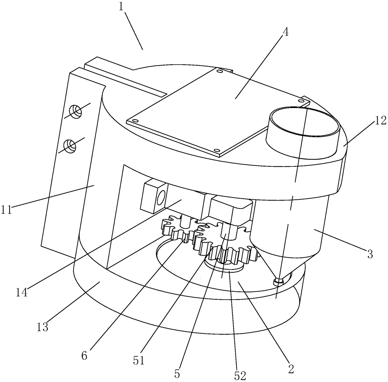
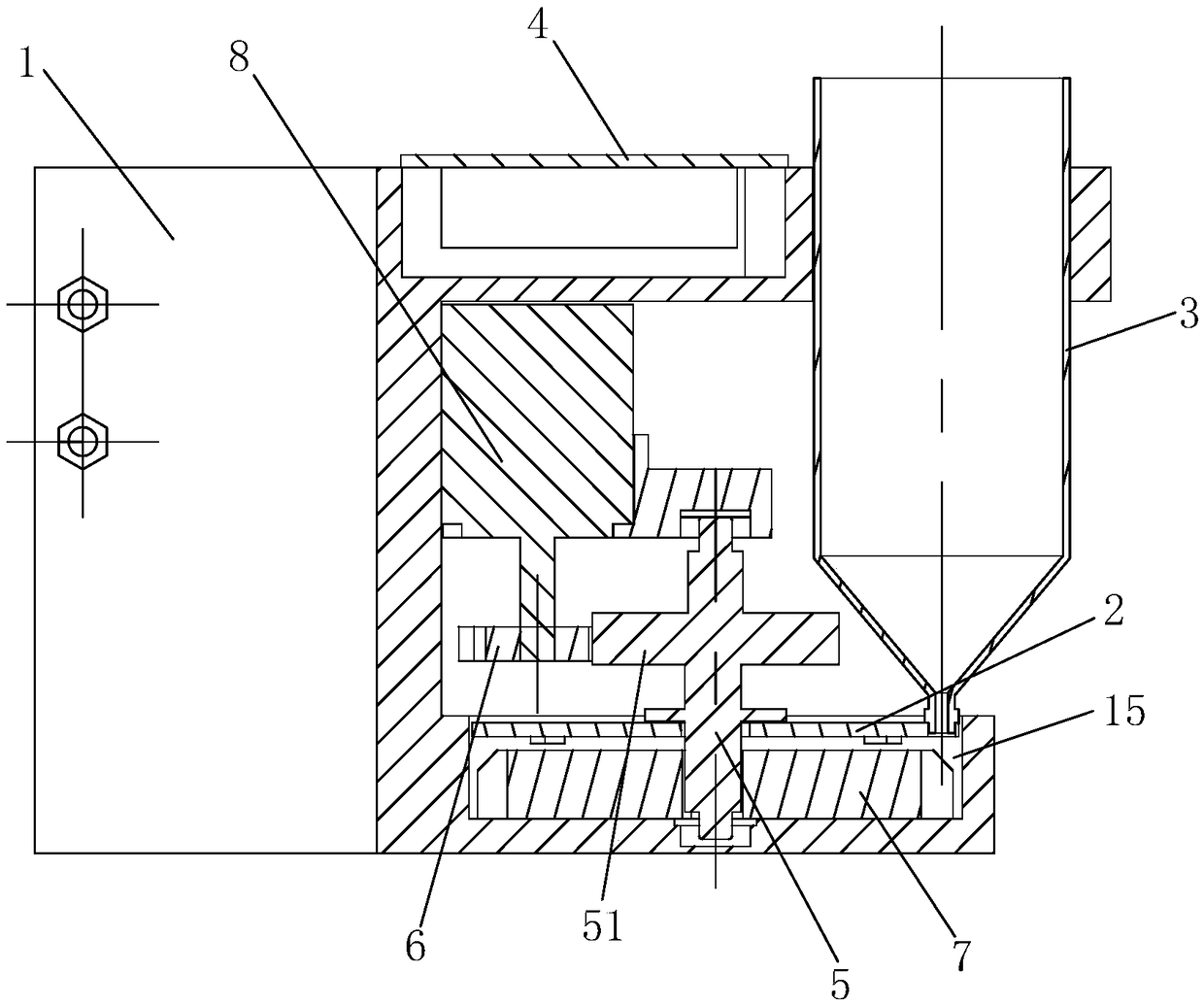
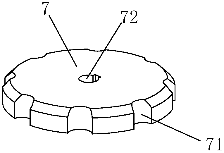
[0027] Examples, see Figure 1-Figure 7 As shown, a self-weight quantitative powder supply device suitable for laser remanufacturing of the present invention includes a body, a drive mechanism, a powder bucket 3, and a powder feeding plate 7. The body is provided with a rotary cavity 15, and the top of the rotary cavity 15 The powder inlet hole 21 on the surface and the powder outlet hole 131 running through the bottom surface of the rotary chamber 15, the powder inlet hole 21 and the powder outlet hole 131 are both deviated from the central axis of the rotary chamber 15, and the two are staggered up and down; the powder bucket 3 is arranged on the body , and the powder drop port at the bottom is connected to the powder inlet hole; the powder feeding disc 7 is rotatably arranged in the rotary chamber 15 around its axis, and is driven to rotate by the drive mechanism arranged on the body. The powder feeding plate 7 is evenly distributed along its circumference with several powd...


PUM


Abstract

The invention discloses a self-weight quantitative powder feeding device applicable to laser remanufacturing. The powder feeding device comprises a body, a driving mechanism, a powder bucket and a powder feeding tray; the body is provided with a rotary cavity, a powder inlet penetrating through the top surface of the rotary cavity, and a powder outlet penetrating through the bottom surface of therotary cavity; the powder inlet and the powder outlet are deviated from the central axis of the rotary cavity and are arranged up and down in a staggered mode; the powder bucket is arranged on the body, and a powder discharging port in the bottom end of the powder bucket communicates with the powder inlet; the powder feeding tray is arranged in the rotary cavity in the mode that the powder feedingtray can rotate around the axis of the powder feeding tray; the powder feeding tray is driven by the driving mechanism arranged on the body to rotate; a plurality of powder feeding structures are distributed on the powder feeding tray circumferentially; the upper end of each powder feeding structure is used as a powder feeding end, and the lower end of each powder feeding structure is used as a powder discharging end; and each powder feeding structure rotates with the powder feeding tray so that the powder feeding end of the powder feeding structure can face the powder inlet vertically or thepowder discharging end of the powder feeding structure can face the powder outlet vertically. Quantitative powder supply can be achieved, powder supply is stable, heat exchange can be reduced, and the powder utilization rate is increased.

Description

technical field [0001] The invention relates to a powder supply device, in particular to a self-weight quantitative powder supply device suitable for laser remanufacturing. Background technique [0002] Laser cladding, also known as laser cladding or laser cladding, is a widely used surface modification technique. During the molding process, the laser hits the substrate with a certain power, and the substrate instantly melts from a solid state into a high-temperature liquid molten pool; powdery materials are added to the molten pool, melted rapidly at high temperature and mixed with the molten pool of the substrate; laser After sweeping, the molten pool is rapidly cooled by ambient temperature to form a new metallurgical layer. Compared with other surface modification technologies such as butt welding, spraying, electroplating and vapor deposition, this method has the characteristics of small dilution, compact structure and wide range of available materials. Most of the po...

Claims


Application Information

Patent Timeline
Patent Type & Authority Applications(China)
IPC IPC(8): C23C24/10
CPCC23C24/10
Inventor 吕培杰颜丙功江开勇路平靳玲胡奔康磊刘斌王霏张际亮顾永华闫茂松
Owner HUAQIAO UNIVERSITY
Why Eureka
Try Eureka