
Film-forming method and film-forming apparatus

A film-forming method and film-forming device technology, which can be used in spraying devices, lighting devices, electrostatic spraying devices, etc., and can solve problems such as inappropriate inkjet methods

Inactive Publication Date: 2019-01-29
OPTNICS PRECISION
View PDF12 Cites 0 Cited by
  • Summary
  • Abstract
  • Description
  • Claims
  • Application Information

AI Technical Summary

Problems solved by technology

Therefore, the size of a segment is 4 times that of a segment of an evaporation block, and the inkjet method is not suitable for display panels requiring high resolution

Method used


Image

  • Film-forming method and film-forming apparatus
  • Film-forming method and film-forming apparatus
  • Film-forming method and film-forming apparatus

Examples


Embodiment Construction

[0036] Hereinafter, embodiments of the film forming method and film forming apparatus of the present invention will be described in detail with reference to the drawings.

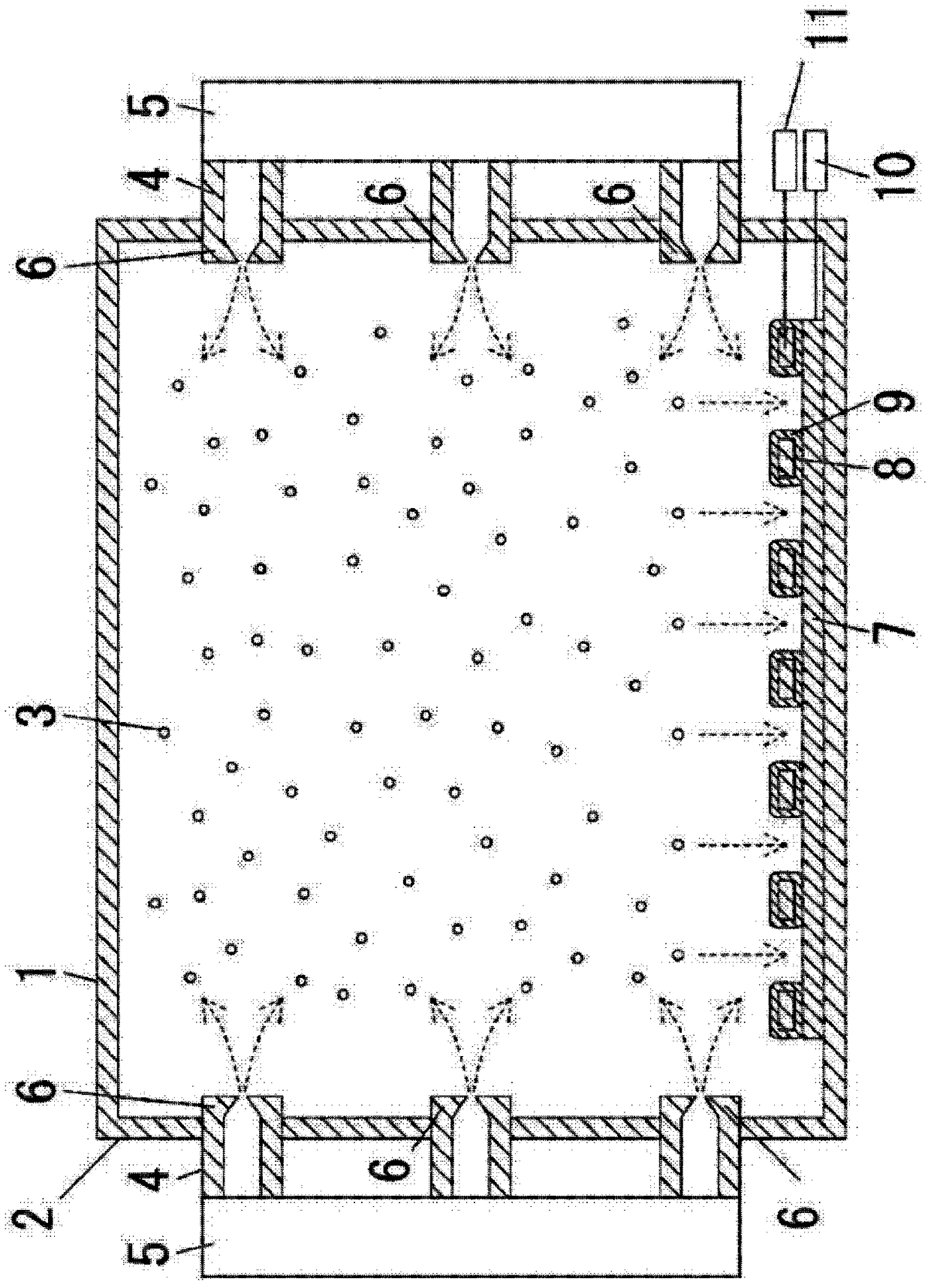
[0037] figure 1 In the figure, 1 is a tank, and the spraying device 5 which has the some nozzle 4 which sprays the microparticles|fine-particles 3 which are film-forming materials from the side wall 2 to the inside of the tank 1 is provided. From this spray device 5, through the piezoelectric element (not shown) that is used for spraying and the nozzle 4 of mesh shape (for example, diameter 1~5 μm, preferably make with the precision of 2.5±0.2 μm), particle diameter is 2~5 μm. Uniform particles 3 of 6 μm, preferably 3.3±0.2 μm, are sprayed into the tank 1 . 6 is a charging device for charging the microparticles 3 with, for example, a negative potential.

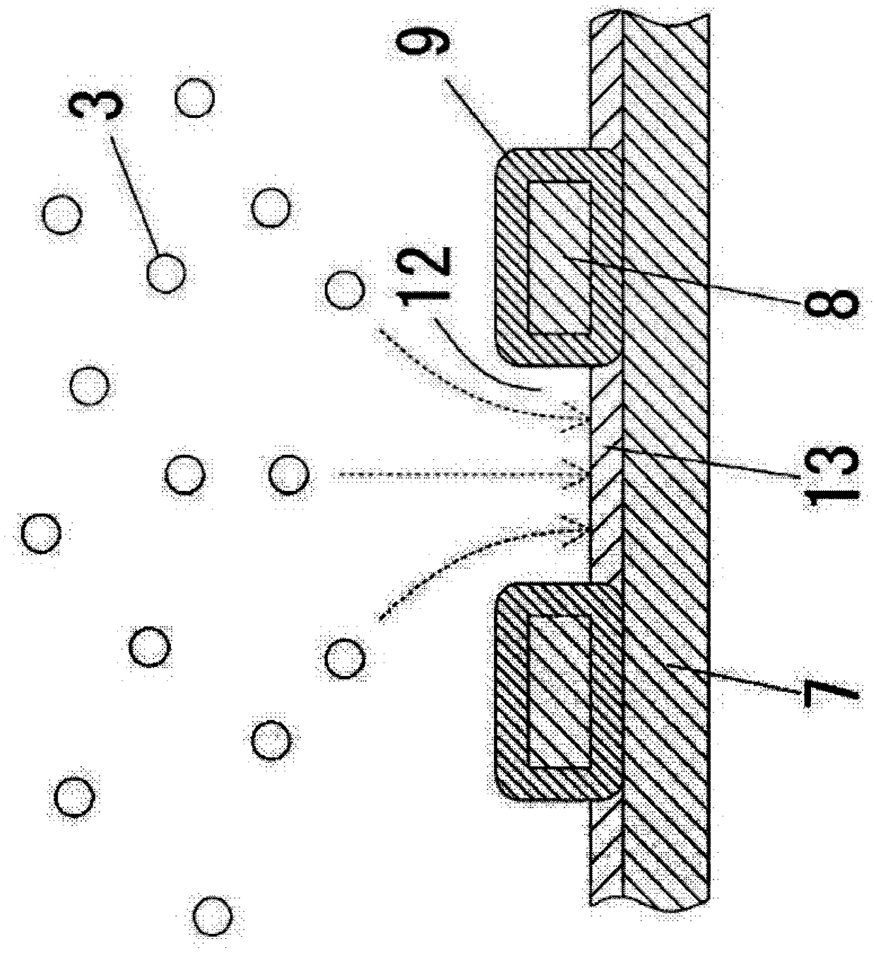
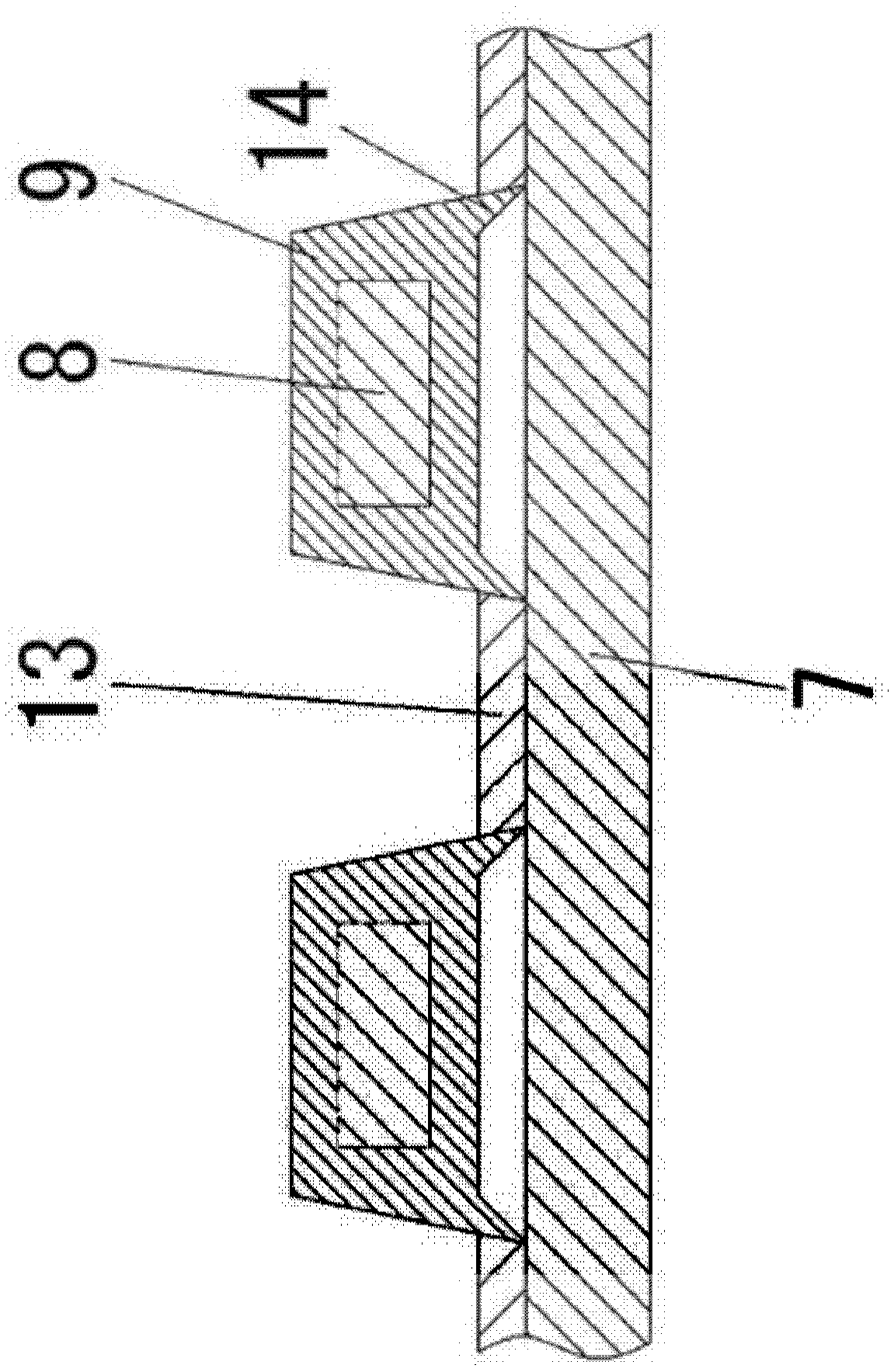
[0038] 7 is a substrate formed of a transparent body, which is provided at the bottom of the tank 1 . On this substrate 7, a mask 8 produced by electro...


PUM


Abstract

In the present invention, a substrate is provided at a bottom section of a tank, a mask is provided on the substrate, with an insulator interposed therebetween, electrically-charged microparticles that serve as a film-forming material are sprayed into the space in the tank, the substrate is conferred a reverse polarity potential from the electrically-charged microparticles, and the mask is conferred the same polarity potential as the electrically-charged microparticles, thereby making the microparticles deposit on the substrate and form a film.

Description

technical field [0001] The present disclosure relates to a film-forming method and a film-forming apparatus for forming a film for producing organic EL (organic electroluminescence) or the like. Background technique [0002] In order to colorize the current organic EL elements, it is necessary to arrange and form RGB light-emitting regions at predetermined positions with high precision. As this film forming technique, a method of forming a thin film by attaching a deposition mask is used, and a printing method such as an inkjet method, a spray method, a spin coating method, a gravure method, a transfer method, etc. is used as a wetting process. [0003] However, since the vapor deposition mask used in the vapor deposition method is affected by temperature changes during vapor deposition, it must be made of a material having the same value as the expansion coefficient of the substrate on which the film is formed. The current situation is to etch the Invar material of the nic...

Claims


Application Information

Patent Timeline
Patent Type & Authority Applications(China)
IPC IPC(8): B05D1/04B05B5/025B05D1/32H01L51/50H05B33/10
CPCB05D1/04H05B33/10B05D1/02B05D3/14B05D1/30B05D1/32B05B5/0255B05B17/0646B05B12/20H10K71/166H01L21/02631H01L21/67017B05B5/025H10K50/11H10K71/00
Inventor 绢田精镇
Owner OPTNICS PRECISION
Learn More