
Eureka
For R&D, Eureka makes reading and utilizing patents & technical documents easy.
Eureka AIR
Designed for self-driven R&D workflows. Generate viable solutions, solve complex R&D challenges, empower your innovation with AI.

Eureka Materials
Designed for material experts only. Revolutionize your material R&D, from search, analyze, to developing new materials.

TechResearch
Generate reliable direction feasibility study reports for your R&D in just a few steps.

TechSeek
Discover and master advanced knowledge NOW. Basics, ideas, possibilities, all at once.

TechMind
As an expert in R&D Theories, TechMind can generates customized viable solutions instantly.

TechRisk
Analyze your overall solution with one click, know your potential R&D risks in advance.

TechMonitor
Get weekly tech updates, stay abreast of the latest tech innovations and key insights.
Moon cake forming machine
A forming machine and forming mechanism technology, applied in dough forming machinery or equipment, disc-shaped dough forming, baking, etc., can solve the problems of offset stamping, incomplete stamping, defective products, etc., and achieve rapid adjustment and guarantee consistent effect
- Summary
- Abstract
- Description
- Claims
- Application Information
AI Technical Summary
Problems solved by technology
Method used
Image

Examples
Embodiment 1
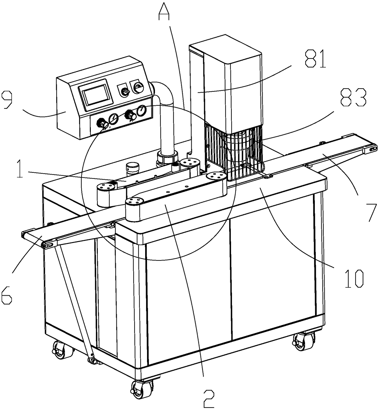
[0042] One of the embodiments of the present invention, such as Figures 1 to 7 As shown, this embodiment provides a moon cake forming machine, including a body, the body is provided with a controller 9 and an operation platform 10, the operation platform 10 is provided with a forming mechanism, and the forming mechanism is connected with the controller 9, The forming mechanism includes a conveyor belt and a pressing die mechanism 8. The pressing die mechanism 8 comprises a pressing die column 81 and a punching die 82. The die pressing column 81 is erected on the operation platform 10, and the punching die 82 is arranged close to the On the press die column 81 on one side of the front conveyor belt 6, a cylinder is arranged above the press die 82, and the press die 82 is driven by the cylinder to move up and down in the vertical direction. The operation platform 10 is arranged horizontally, and the vertical direction in this embodiment is the direction perpendicular to the dir...
Embodiment 2
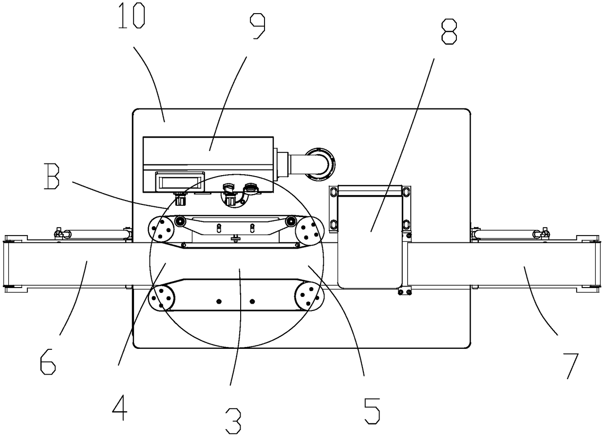
[0048] One of the embodiments of the present invention, as shown in the figure, the main technical solution of this embodiment is basically the same as that of Embodiment 1, and the features that are not explained in this embodiment are explained in Embodiment 1, and will not be repeated here. Repeat. The difference between this embodiment and Embodiment 1 is that the part of the front conveyor belt 6 extending out of the operation platform 10 is formed as an input end, the part of the rear conveyor belt 7 extending out of the operation platform 10 is formed as an output end, and the front conveyor belt 7 is formed as an output end. The transmission belt 6 and the rear transmission belt 7 rotate along the direction from the input end to the output end; the rotating structures of the above-mentioned front and rear transmission belts are all rotated by setting a plurality of guide wheels for linkage. In addition, the plurality of guide wheels can stretch the front conveyor belt ...
Embodiment 3
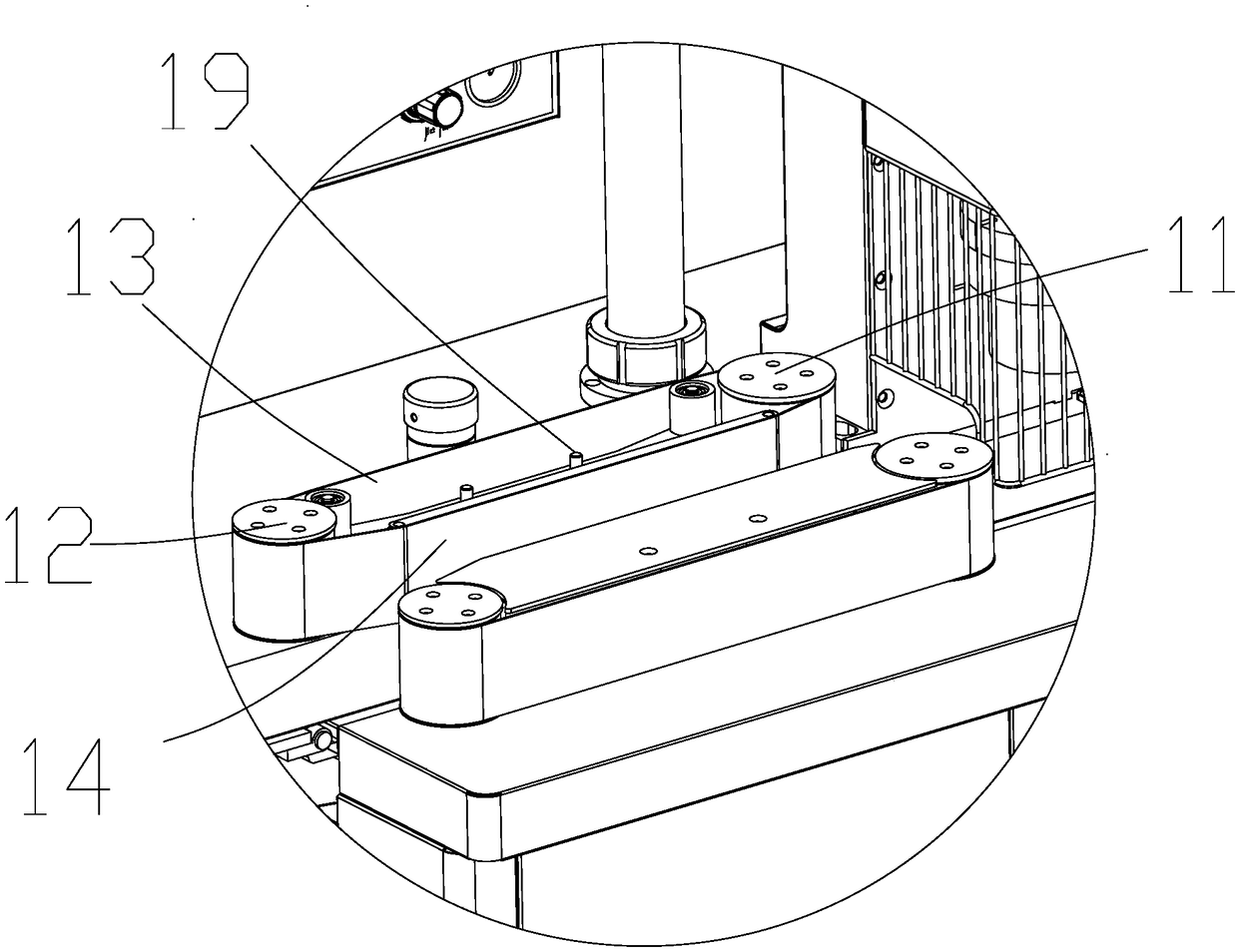
[0067] As one of the embodiments of the present invention, as shown in the figure, the main technical solution of this embodiment is basically the same as that of Embodiment 1 or Embodiment 2, and the features that are not explained in this embodiment are adopted in Embodiment 1 or Embodiment 2 The explanations in , will not be repeated here. The difference between this embodiment and Embodiment 1 or Embodiment 2 is that a longitudinal frame plate 115 is erected downward in the middle of the operation platform 10 , and a linkage rod 101 is laterally arranged on the longitudinal frame plate 115 . A first synchronous rotating tooth 102 is provided at the position corresponding to the position of the first rotating module 1, and a second synchronous rotating tooth 103 is disposed corresponding to the position of the second rotating module 2;
[0068] The first rotating group 1 is extended downward with a first linkage tooth 104 that is linked with the first rotating group 1. Furt...
PUM
 Abstract
Description
Claims
Application Information
 - R&D Engineer
- R&D Manager
- IP Professional
- Industry Leading Data Capabilities
- Powerful AI technology
- Patent DNA Extraction
Browse by: Latest US Patents, China's latest patents, Technical Efficacy Thesaurus, Application Domain, Technology Topic, Popular Technical Reports.
© 2024 PatSnap. All rights reserved.Legal|Privacy policy|Modern Slavery Act Transparency Statement|Sitemap|About US| Contact US: help@patsnap.com