Car shaft punching device

A technology for punching devices and automobile axles, which is applied in the direction of feeding devices, positioning devices, storage devices, etc., and can solve the problems of no way to clamp and fix automobile axles

Active Publication Date: 2019-02-01
龙口市中达机械设备有限公司
View PDF6 Cites 2 Cited by
  • Summary
  • Abstract
  • Description
  • Claims
  • Application Information

AI Technical Summary

Problems solved by technology

[0002] For example, the patent number is CN201621371700.2 a kind of punching device, including a support block 1, a limit block a2, a limit block b3, a pressing block 4, a quick clamp 5 and a base plate 6, wherein the support block 1 is arranged on the base plate 6, the left side and rear side of the support block (1) are respectively provided with a limit block a2 and a limit block b3 for positioning the product sideways, and the pressing block 4 is arranged on the right side of the support block 1 and the quick clamp 5 connection, and the clamping and loosening of the product is controlled by the quick clamp 5, which is installed on the base plate 6, but the disadvantage of this invention is that there is no way to clamp and fix automobile axles of different specifications

Method used


Image

  • Car shaft punching device
  • Car shaft punching device
  • Car shaft punching device

Examples


specific Embodiment approach 1

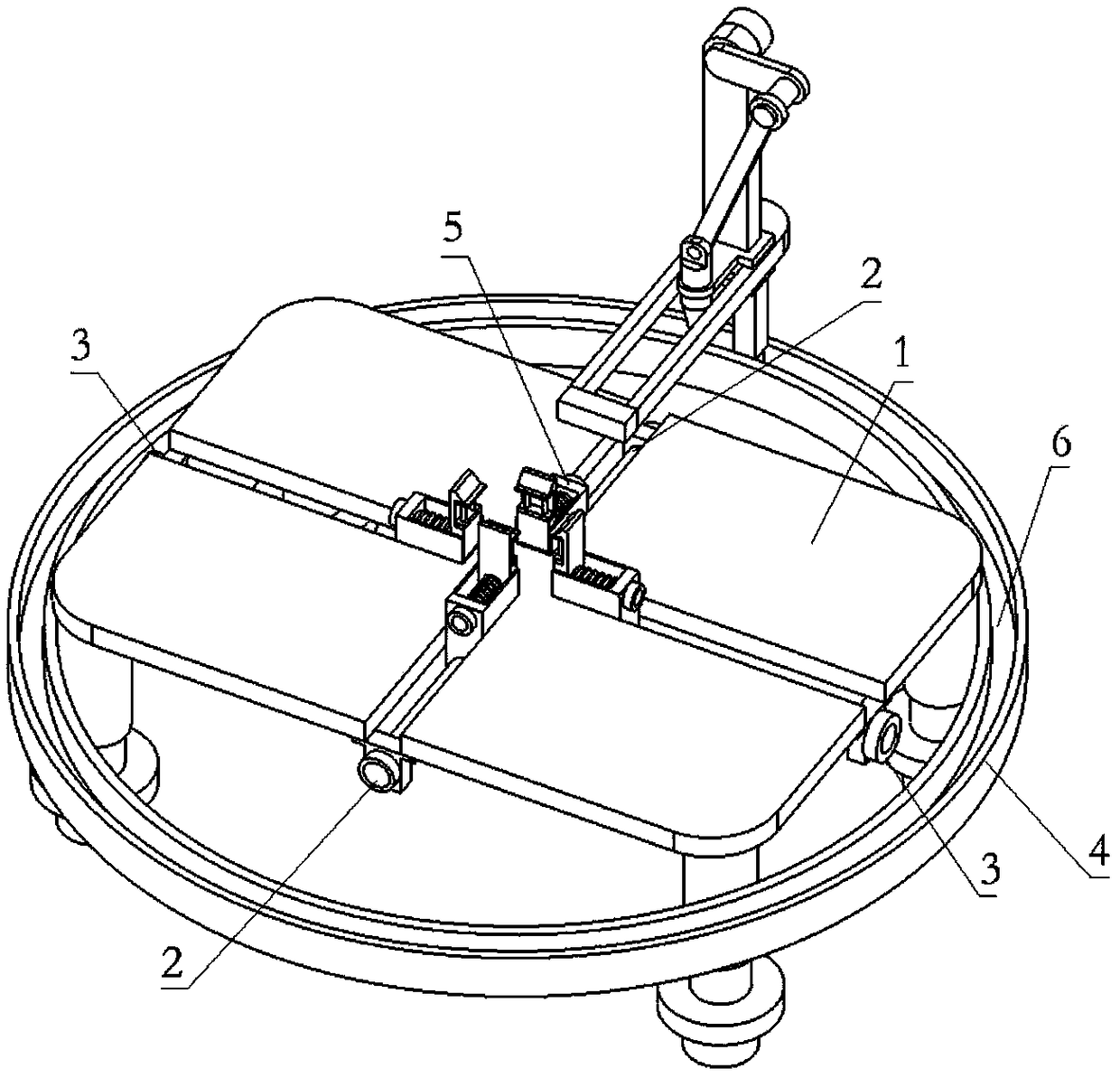
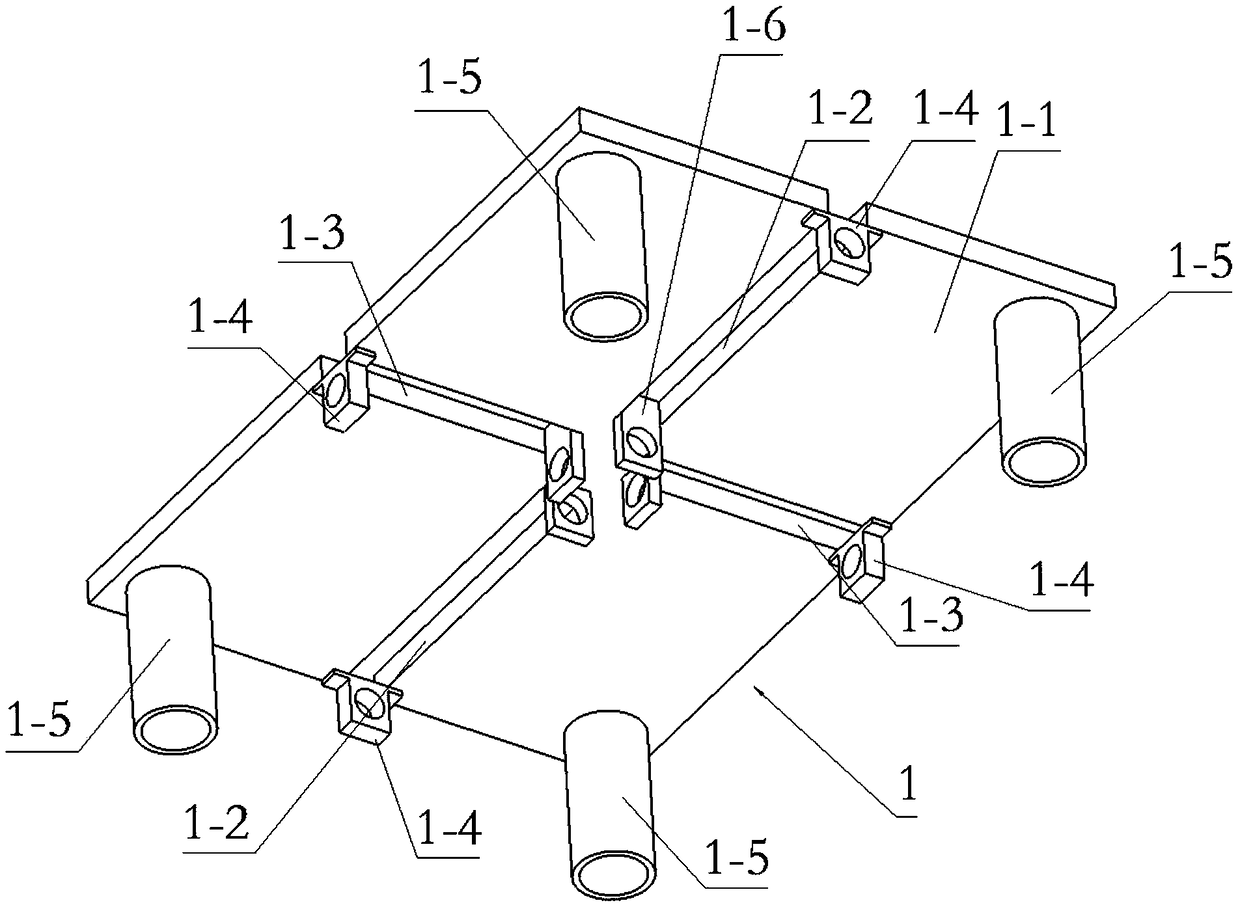
[0033] Combine below Figure 1-14 Describe this embodiment, a kind of punching device for automobile shafts, including a chassis body 1 and four clip bodies 5, the chassis body 1 includes a bottom plate 1-1, two longitudinal chute 1-2, two transverse Chutes 1-3, four hinged terminals 1-4, four bushings 1-5 and four inner hinged plates 1-6, two longitudinal chutes 1-2 are respectively arranged at the left and right ends of the bottom plate 1-1 , two transverse slide grooves 1-3 are respectively arranged at the front and rear ends of the bottom plate 1-1, four hinged terminals 1-4 are respectively fixedly connected to the middle ends of the four sides of the bottom surface of the bottom plate 1-1, and four bushings 1-5 are respectively fixedly connected to the four corners of the bottom surface of the bottom plate 1-1, and the four inner hinge plates 1-6 are respectively fixedly connected to the two longitudinal chute 1-2 and the two transverse chute 1-3. inner end;

[0034] T...

specific Embodiment approach 2

[0037] Combine below Figure 1-14 This embodiment will be described. This embodiment will further describe the first embodiment, the length of the longitudinal chute 1-2 is greater than the length of the horizontal chute 1-3.

specific Embodiment approach 3

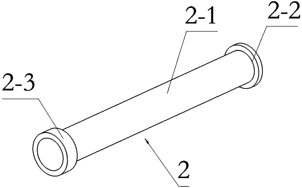
[0038] Combine below Figure 1-14 This embodiment will be described. This embodiment will further describe Embodiment 1. The transverse screw 2 includes a transverse screw body 2-1, a transverse boss 2-2 and a transverse runner 2-3, and the transverse boss 2-2 and the transverse The runners 2-3 are respectively fixedly connected to the two ends of the transverse screw body 2-1, and the inner ends of the two transverse screw bodies 2-1 are respectively rotatably connected to the inner hinge plates 1-6 on the front and rear sides of the bottom plate 1-1, The outer ends of the two transverse screw bodies 2-1 are respectively rotatably connected to the hinge terminals 1-4 on the front and rear sides of the base plate 1-1, and the inner hinge plates 1-6 and hinge terminals 1-4 on the front and rear sides of the base plate 1-1 Both are arranged between the transverse boss 2-2 and the transverse runner 2-3, and the clip bodies 5-1 in the two transverse chute 1-3 are connected to the ...


PUM


Abstract

The invention relates to a punching device, in particular to a car shaft punching device. Different specifications of car shafts can be fixed, the fixed car shafts can be punched, and the to-be-punched positions of the fixed car shafts can be adjusted. The car shaft punching device comprises an underframe body and four clip bodies, wherein the underframe body comprises a bottom plate, two longitudinal chutes, two transverse chutes, four hinged ends, four sleeves and four inner hinged plates, and the two longitudinal chutes, the two transverse chutes, the four hinged ends, the four sleeves andthe four inner hinged plates are conveniently connected by virtue of the bottom plate; the four clip bodies are conveniently arranged at the two longitudinal chutes and the two transverse chutes; twovertical sliding rods are conveniently arranged in two vertical sliding holes; the two vertical sliding rods are conveniently connected in a sliding mode by virtue of the two vertical sliding holes; the back ends of sliding columns in the sliding holes can be limited by limiting sleeves, so that the sliding columns cannot be disengaged from the sliding holes; and two inner springs are compressed,so that the two vertical sliding rods are far from the bottom ends of the two vertical sliding rods.

Description

technical field [0001] The invention relates to a punching device, in particular to a punching device for automobile axles. Background technique [0002] For example, the patent number is CN201621371700.2 a kind of punching device, including a support block 1, a limit block a2, a limit block b3, a pressing block 4, a quick clamp 5 and a base plate 6, wherein the support block 1 is arranged on the base plate 6, the left side and rear side of the support block (1) are respectively provided with a limit block a2 and a limit block b3 for positioning the product sideways, and the pressing block 4 is arranged on the right side of the support block 1 and the quick clamp 5, and control the clamping and unclamping of the product through the quick clamp 5, the quick clamp 5 is installed on the base plate 6, but the shortcoming of this invention is that there is no way to clamp and fix the automobile axles of different specifications. Contents of the invention [0003] The object of...

Claims


Application Information

Patent Timeline
Patent Type & Authority Applications(China)
IPC IPC(8): B21D28/32B21D28/34B21D43/00
CPCB21D28/32B21D28/34B21D43/003
Inventor 郭淑梅
Owner 龙口市中达机械设备有限公司
Why Eureka
Try Eureka