An automatic positioning device for tapping and feeding the filter cover
An automatic positioning and filter cover technology, which is applied in the direction of tangential feeding device, tangential device, metal processing equipment, etc., can solve the problem of filter cover damage, filter cover fixation, and adjustment disc can not effectively drive the filter Problems such as the cover and the like, to achieve the effect of quick positioning
- Summary
- Abstract
- Description
- Claims
- Application Information
AI Technical Summary
Problems solved by technology
Method used
Image
Examples
Embodiment 1
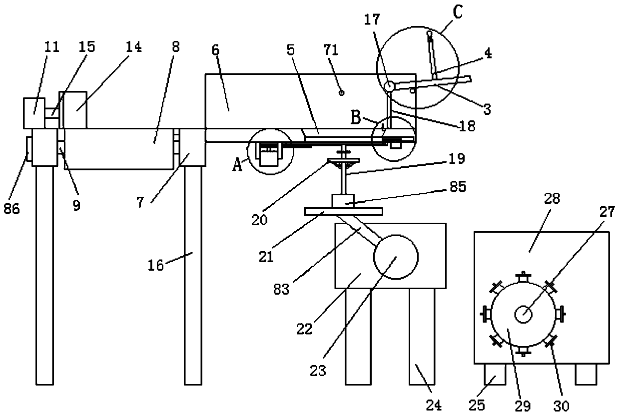
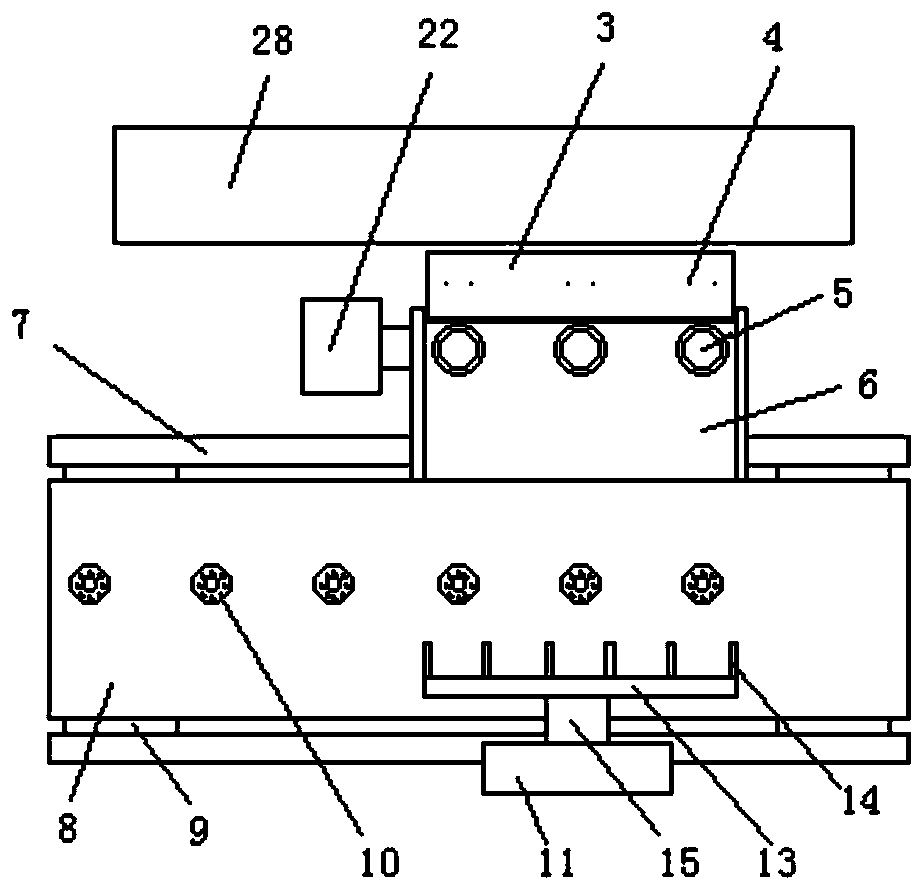
[0046] Embodiment 1, an automatic positioning device for tapping and feeding a filter cover, including an automatic tapping machine 28 and a filter cover 10, the middle part of the filter cover 10 is provided with a connecting hole 67, and the connecting hole 67 is located The outer side is provided with a number of fixed holes 66 that are evenly and centrally symmetrically distributed, and a conveyor belt 8 is provided on one side of the automatic tapping machine 28, and a diversion groove is provided on the conveyor belt 8 near the automatic tapping machine 28 side. 6. The diversion groove 6 is provided with a number of feed grooves 5 that are evenly distributed and matched with the tapping fixing holder 30 in the automatic tapping machine 28, and the bottom of the feed groove 5 is provided with a filter cover. 10 matched positioning grooves 38, the bottom of the positioning groove 38 is provided with a material retaining plate 34, and the two ends of the material retaining p...
Embodiment 2
[0052] The same as embodiment 1 is no longer repeated, and the difference with embodiment 1 is:
[0053] Preferably, the bottom of the transfer motor 22 is provided with a number of evenly distributed second fixing brackets 24, the transfer disc 21 is provided with a second hydraulic rod 19, and the transfer disc 21 is provided with a second hydraulic rod. The second electro-hydraulic driving device 85 matched with the rod 19, the second hydraulic rod 19 is provided with the tray 20, the transfer rod 68 is arranged at the upper end of the tray 20, and the middle part of the transfer rod 68 is provided with a snap ring 67 . Utilizing the lifting of the second hydraulic rod, the transfer rod can be recovered to the initial position after receiving the filter cover, so that the transfer rod can not touch the bottom of the diversion groove when rotating, so that the whole device can Complete operation, and the control of the hydraulic rod improves the overall control accuracy, ma...
Embodiment 3
[0056] The same as embodiment 1 is no longer repeated, and the difference with embodiment 1 is:
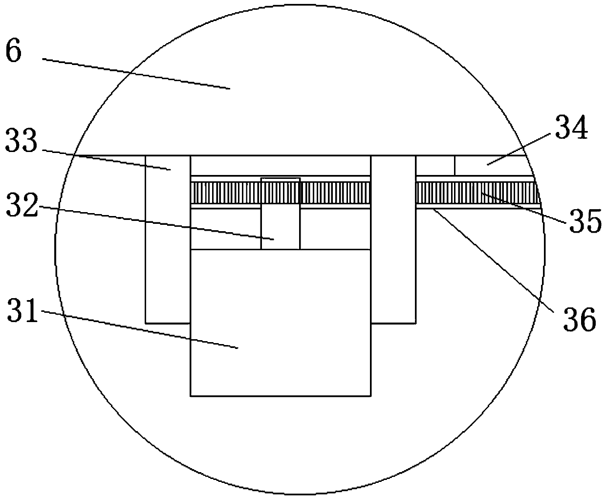
[0057] Preferably, the bottom of the diversion groove 6 located inside the positioning groove 5 is provided with a second adjustment motor 31, and the second adjustment motor 31 is fixed on the bottom of the diversion groove 6 by a second fixing rod 33. The upper end of the motor 31 is provided with an output shaft 32, the output shaft 32 is provided with a first gear 46, the bottom of the baffle plate 34 is provided with a fixedly connected discharge rod 36, and the side of the discharge rod 36 is provided with a number of uniform gears. Distributed first racks 35 , the discharge rod 36 is connected to the second adjusting motor 31 through the first gear 46 and the first rack 35 meshing with each other. The second regulating motor is used to drive the rapid movement of the material retaining plate through gear transmission, thereby realizing the automatic opening and closing of t...
PUM
| Property | Measurement | Unit |
|---|---|---|
| thickness | aaaaa | aaaaa |
Abstract
Description
Claims
Application Information
 - R&D
- Intellectual Property
- Life Sciences
- Materials
- Tech Scout
- Unparalleled Data Quality
- Higher Quality Content
- 60% Fewer Hallucinations
Browse by: Latest US Patents, China's latest patents, Technical Efficacy Thesaurus, Application Domain, Technology Topic, Popular Technical Reports.
© 2025 PatSnap. All rights reserved.Legal|Privacy policy|Modern Slavery Act Transparency Statement|Sitemap|About US| Contact US: help@patsnap.com


