Supercharge Your Innovation With Domain-Expert AI Agents!

Auto Triangular Window Injection Mold

A technology for injection molds and triangular windows, applied in the field of molds, can solve the problems of no air extraction and sealing, low yield rate, affecting product quality, etc., and achieve the effect of protecting from damage, improving yield rate, and high practicability

Active Publication Date: 2021-10-12
佛山市顺德区杰润五金塑料有限公司
View PDF5 Cites 0 Cited by
  • Summary
  • Abstract
  • Description
  • Claims
  • Application Information

AI Technical Summary

Problems solved by technology

[0003] After retrieval, the authorized announcement number is CN204249259U, which discloses an injection mold for auto parts, including an upper mold and a lower mold. The upper mold is provided with a liquid injection hole, which communicates with the flow channel in the upper mold. There is a lock pin at the four top corners of the upper surface, the lower mold is placed on the rotating disk, the bottom of the lower mold is connected with the output shaft of the rotating cylinder set in the rotating disk, and the heating pipeline is evenly laid in the lower mold , the heating pipes are also filled with heat-conducting materials, and a vibrating block is connected to one side wall of the lower mold. The lower movement is used to discharge the air in the mold cavity and eliminate the air holes in the injection molded parts after injection molding. The vibrating block drives the mold to vibrate, which ensures the uniformity of the injection solution in the lower mold cavity and improves the quality of the injection molded product; it has a simple structure , easy to use, high injection molding efficiency, and good injection molding effect, etc., but the above design still has shortcomings, it does not have the function of pumping and sealing, and cannot extract and seal the air in the molding cavity, which affects the quality of the product. In addition, it does not With ejection mechanism, it is not convenient to take out the finished triangular window, which may easily lead to damage when taking out the product, and the yield rate is low

Method used


Image

  • Auto Triangular Window Injection Mold
  • Auto Triangular Window Injection Mold
  • Auto Triangular Window Injection Mold

Examples


Embodiment

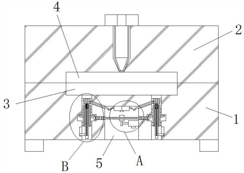
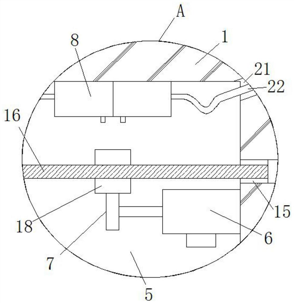
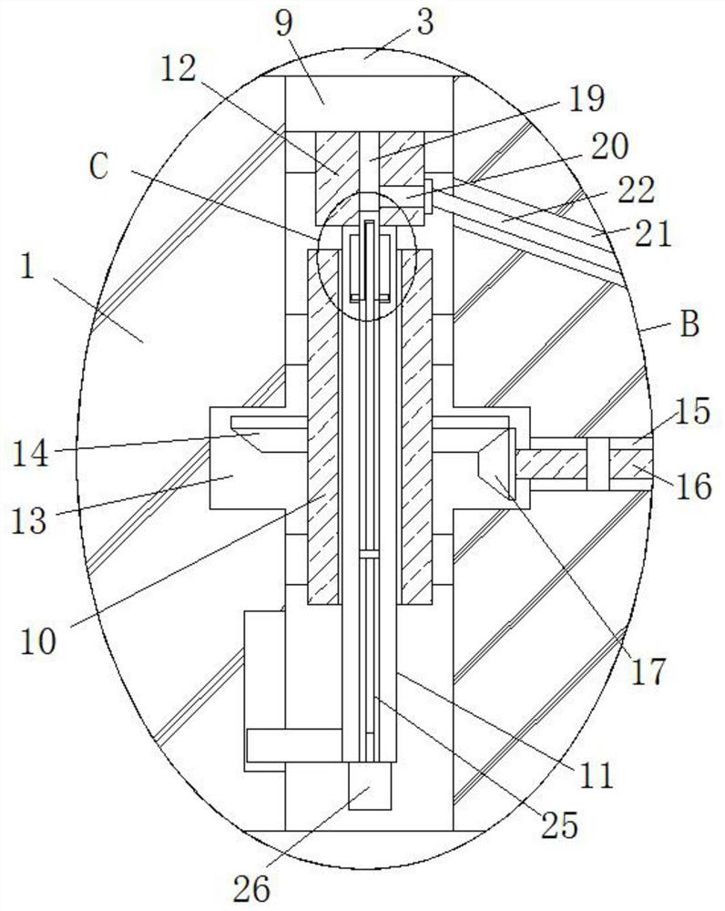
[0025] refer to Figure 1-5 In this embodiment, the car triangle window injection mold is proposed, including the lower mold 1, and the top of the lower mold 1 is provided with upper mold 2, and the top of the lower mold 1 is opened, and the bottom mold 2 is opened. The forming chamber 4, the lower cavity 3 and the upper forming chamber 4 are adapted, and the bottom of the lower mold 1 is opened, and the first motor 6 is fixedly installed on one side of the first groove 5, the first The first gear 7 is welded to the output shaft of the motor 6, and two pumping pumps 8 are fixedly mounted on the top inner wall of the first recess 5, and two first through holes 9, the bottom of the lower cavity 3 are opened. The inner thread sleeve 10 is rotated in the through hole 9, and the inner threaded sleeve 10 is applied to the first wire rod 11, and the top and bottom ends of the first thread rod 11 extend to the inner thread sleeve 10, and The top end of the first thread rod 11 is welded wit...


PUM


Abstract

The invention belongs to the technical field of moulds, in particular to a triangular window injection mold for automobiles, comprising a lower mold, an upper mold is arranged on the top of the lower mold, and a lower molding cavity is opened on the top of the lower mold, and an upper mold is opened on the bottom of the upper mold. The molding cavity, the lower molding cavity and the upper molding cavity are compatible, the bottom of the lower mold is provided with a first groove, the first motor is fixedly installed on the inner wall of one side of the first groove, and the output shaft of the first motor is welded with The first gear and the top inner wall of the first groove are fixedly equipped with two suction pumps. The present invention has high practicability and simple operation. The air in the molding cavity can be quickly drawn out and sealed through the cooperation of the air pump, the second motor, the sealing block and the hose, thereby improving the quality of the product. At the same time, the first motor provides The power can quickly close the fourth through hole, and can quickly eject the formed product, effectively protecting the product from damage and improving the yield rate.

Description

Technical field [0001] The present invention relates to the field of mold, in particular to a car triangle window injection mold. Background technique [0002] With the continuous development of technology, the automotive industry has made great progress, and a large number of auto parts are produced. The current automotive appearance fittings have been concerned, especially in appearance plastic parts, such as triangular windows, front baffles and rear baffles. Wait, the triangle window is more complicated, and the mold is injection molded. [0003] The instead of the retrieval, the authorized bulletin is an automotive parts disclosed in CN204249259U, including upper mold and lower mold, and a nichery hole, the liquid hole is connected to the flow path in the upper mold, in the lower mold At the four top angles of the upper surface, there is a lock pin, and the lower mold is placed on the rotating disk, and the bottom of the lower mold is connected to the output shaft of the rot...

Claims


Application Information

Patent Timeline
Patent Type & Authority Patents(China)
IPC IPC(8): B29C45/26B29C45/34B29C45/40
CPCB29C45/26B29C45/34B29C45/401B29C2045/4036
Inventor 查国东储振亚储亮李云雷查卫东程志刚
Owner 佛山市顺德区杰润五金塑料有限公司
Features
  • R&D
  • Intellectual Property
  • Life Sciences
  • Materials
  • Tech Scout
  • Unparalleled Data Quality
  • Higher Quality Content
  • 60% Fewer Hallucinations
Learn More