Tire frame for assembly of automobile tire

A technology for automobile tires and tire racks, applied in the field of tire racks, can solve the problems of reducing tire installation speed and high labor intensity, and achieve the effects of preventing excessive strain and breaking and preventing shaking.

Inactive Publication Date: 2019-02-01
王东明
View PDF0 Cites 3 Cited by
  • Summary
  • Abstract
  • Description
  • Claims
  • Application Information

AI Technical Summary

Problems solved by technology

[0003] In order to overcome the shortcoming of needing to manually hold the car tire and continuously rotate the car tire to align with the bolts on the car, such artificial labor i

Method used


Image

  • Tire frame for assembly of automobile tire
  • Tire frame for assembly of automobile tire

Examples


Embodiment 1

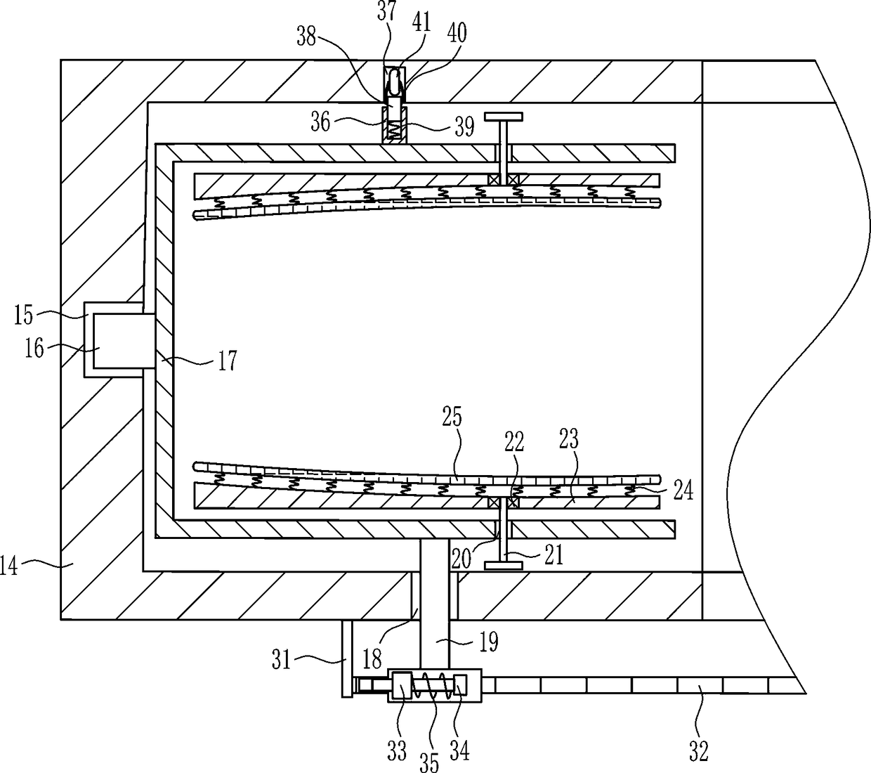
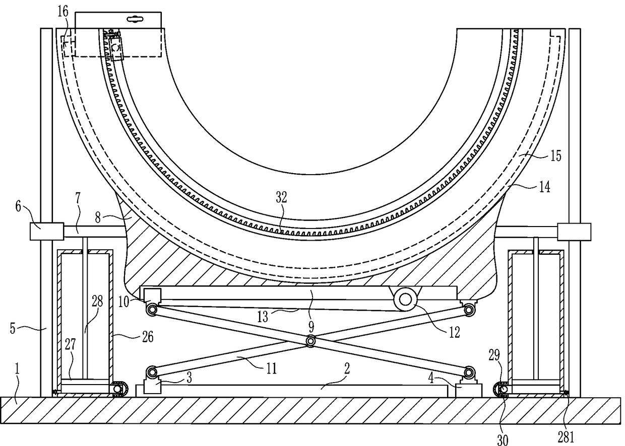
[0020] A tire frame for automobile tire assembly, such as Figure 1-2 As shown, it includes a bottom plate 1, a sliding rail 2, a first sliding block 3, a fixed block 4, a sliding rod 5, a sliding sleeve 6, a connecting plate 7, a mounting plate 8, a second sliding block 10, a cross-type lifting frame 11, The electric reel 12, the pulling rope 13, the placing frame 14, the third slider 16, the n-shaped frame 17 and the T-shaped handle 19, the top of the bottom plate 1 is connected with a sliding rail 2, and the sliding rail 2 is provided with a first sliding block 3. The bottom plate 1 on the right side of the slide rail 2 is connected with a fixed block 4, and the left and right sides of the top of the bottom plate 1 are connected with a slide bar 5. The slide rail 2 and the fixed block 4 are located between the two slide bars 5, and the slide bar 5 There is a sliding sleeve 6 on it, the inner sides of the two sliding sleeves 6 are connected with a connecting plate 7, and a m...

Embodiment 2

[0022] A tire frame for automobile tire assembly, such as Figure 1-2As shown, it includes a bottom plate 1, a sliding rail 2, a first sliding block 3, a fixed block 4, a sliding rod 5, a sliding sleeve 6, a connecting plate 7, a mounting plate 8, a second sliding block 10, a cross-type lifting frame 11, The electric reel 12, the pulling rope 13, the placing frame 14, the third slider 16, the n-shaped frame 17 and the T-shaped handle 19, the top of the bottom plate 1 is connected with a sliding rail 2, and the sliding rail 2 is provided with a first sliding block 3. The bottom plate 1 on the right side of the slide rail 2 is connected with a fixed block 4, and the left and right sides of the top of the bottom plate 1 are connected with a slide bar 5. The slide rail 2 and the fixed block 4 are located between the two slide bars 5, and the slide bar 5 There is a sliding sleeve 6 on it, the inner sides of the two sliding sleeves 6 are connected with a connecting plate 7, and a mo...

Embodiment 3

[0025] A tire frame for automobile tire assembly, such as Figure 1-2 As shown, it includes a bottom plate 1, a sliding rail 2, a first sliding block 3, a fixed block 4, a sliding rod 5, a sliding sleeve 6, a connecting plate 7, a mounting plate 8, a second sliding block 10, a cross-type lifting frame 11, The electric reel 12, the pulling rope 13, the placing frame 14, the third slider 16, the n-shaped frame 17 and the T-shaped handle 19, the top of the bottom plate 1 is connected with a sliding rail 2, and the sliding rail 2 is provided with a first sliding block 3. The bottom plate 1 on the right side of the slide rail 2 is connected with a fixed block 4, and the left and right sides of the top of the bottom plate 1 are connected with a slide bar 5. The slide rail 2 and the fixed block 4 are located between the two slide bars 5, and the slide bar 5 There is a sliding sleeve 6 on it, the inner sides of the two sliding sleeves 6 are connected with a connecting plate 7, and a m...


PUM


Abstract

The invention relates to a tire frame, in particular to a tire frame for assembly of an automobile tire. According to the tire frame for assembly of the automobile tire, the labor intensity can be lowered, and the automobile tire mounting speed can be increased. According to the technical scheme, the tire frame for assembly of the automobile tire comprises a bottom plate, a sliding rail, a first sliding block, a fixing block, sliding rods, sliding sleeves, connecting plates, a mounting plate, a second sliding block, a cross lifting frame and the like; the sliding rail is connected to the top of the bottom plate, the first sliding block is arranged on the sliding rail, and the fixing block is connected to the position, on the right side of the sliding rail, of the bottom plate; and the sliding rods are connected to the left and right sides of the top of the bottom plate correspondingly, and the sliding rail and the fixing block are located between the two sliding rods. A T-shaped handleof the tire frame moves, thus an n-shaped frame can drive the automobile tire to move, when a hole position of the automobile tire and a bolt on an automobile coincide, people uses a tool to mount the automobile tire on an automobile and screw a front T-shaped screw rod and a rear T-shaped screw rod by hands simultaneously clockwise, and thus a front rubber plate and a rear rubber plate can get close to each other.

Description

technical field [0001] The invention relates to a tire frame, in particular to a tire frame for assembling automobile tires. Background technique [0002] When installing the car tires, it is necessary to manually hold the car tires for installation. Since the car tires are heavy, it is not convenient to install the car tires manually. When installing the car tires, the car tires need to be manually moved to the car tires. Place, then manually align the holes on the car tires with the bolts on the car, then manually place the car tires on the bolts of the car, and then manually install the car tires with tools. When aligning the bolts on the car tires, it is necessary to manually rotate the car tires continuously, so the labor intensity of the labor is relatively large, which will reduce the installation speed of the car tires. SUMMARY OF THE INVENTION [0003] In order to overcome the need to manually hold the tires and constantly rotate the tires to align with the bolts...

Claims


Application Information

Patent Timeline
IPC IPC(8): B60B29/00B66F7/06
CPCB60B29/001B66F7/065
Inventor 王东明
Owner 王东明
Why Eureka
Try Eureka