
Steel structure bridge connecting device

A connecting device and steel structure technology, applied in the direction of thin plate connection, connecting components, mechanical equipment, etc., can solve the problems of bolt fatigue fracture, weakening strength, changing the stress state of the structure, etc., so as to alleviate the sliding phenomenon, prevent the bolt from falling off, The effect of avoiding rigid failure

Inactive Publication Date: 2019-02-01
SHENYANG JIANZHU UNIVERSITY
View PDF0 Cites 2 Cited by
  • Summary
  • Abstract
  • Description
  • Claims
  • Application Information

AI Technical Summary

Problems solved by technology

[0005] Today, the main disadvantages of bolted connections are as follows: 1. The machining accuracy of components is required to be high, and the friction surface needs special protection, which increases the cost; 2. The force of each bolt in the bolt group cannot be completely uniform, and some bolts may be ahead of schedule. Fatigue fracture, resulting in loss; 3. Mainly high-strength bolts, due to the loss of tensile stress, or quality problems during construction, will cause the friction surface to shift, change the stress state of the structure, and there is a risk of instability; 4. The bolt connection must be opened, which weakens the strength of the section and causes stress concentration; 5. The quality of the bolt itself is unstable, and there will always be some quality fluctuations. Some bolts are defective products when they leave the factory. used in structures where there is a danger

Method used


Image

  • Steel structure bridge connecting device
  • Steel structure bridge connecting device
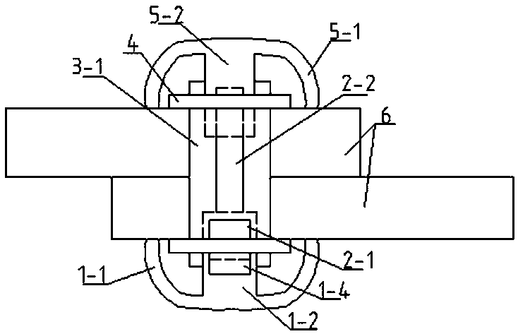
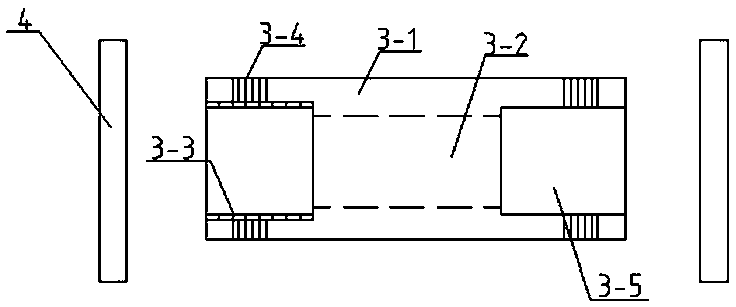
  • Steel structure bridge connecting device

Examples


Embodiment Construction

[0022] In order to further illustrate the present invention, the present invention will be described in detail below in conjunction with the accompanying drawings and embodiments, but they should not be construed as limiting the protection scope of the present invention.

[0023] Such as Figure 1~3 As shown, a steel structure bridge connecting device of the present invention mainly comprises a left bolt cap, a bolt inner rod, a bolt outer rod, a nut, a right bolt cap, and the outside of the left bolt cap is a left friction cap 1-1, and the left friction cap 1-1 The bottom of the inner surface of -1, the thick screw 1-2 is vertically connected with the left friction cap 1-1, the center of the top axis of the thick screw 1-2 is set with the inner hole 1-4 of the thick screw, and the outer surface of the thick screw 1-1 forms a thick screw Thread 1-3, the head of the bolt inner rod is the plug head 2-1, the plug head 2-1 is connected with the bolt inner rod shaft 2-2, and the ou...


PUM


Abstract

The invention discloses a steel structure bridge connecting device. The steel structure bridge connecting device comprises a left bolted cap and a right bolted cap, and the outer part of the left bolted cap is a left friction cap. A plug is inserted into an inner hole of a thick screw, a bolt outer rod penetrates through a bolt inner rod, a thread of the bolt outer rod and the thick screw are twisted in a threaded mode, and the plug is clamped in an inner hole of a thin screw by the side wall of the inner hole of the bolt outer rod. The side wall of a rod body of the bolt outer rod is tightlyattached to the side wall of a rod body of the bolt inner rod, and the thin screw is inserted into the inner hole of the bolt outer rod. The outer wall of thin screw is tightly attached to the side wall of inner hole of the bolt outer rod, the inner hole of the thin screw surrounds the bottom of the rod body of the bolt inner rod, and a thread of the inner hole of the thin screw and a thread of the rod body of the bolt inner rod are twisted in a threaded mode. Nuts are arranged at the left and right ends of the steel structure bridge connecting device, the bolted caps are further additionallyarranged, a bolt is effectively prevented from falling off, meanwhile, the contact area with a connecting plate is increased, the friction surface is effectively increased, the connection quality is improved, the slip phenomenon is alleviated, when an earthquake comes, and the plug produces a small displacement in the inner hole of the thick screw, so that rigid damage is avoided.

Description

technical field [0001] The invention belongs to the technical field of steel structure facilities, in particular to a steel structure bridge connecting device. Background technique [0002] With the rapid progress of society and the increasing technological progress of steel structure bridges in all aspects, steel structure bridges have been widely used. With the development of my country's economy and the further demand for living space, steel structure bridges have great room for development. [0003] The development of my country's iron and steel industry has provided a solid material foundation for the development of steel structure bridges. There are already many professional bridge factories in our country that produce professional steel structure components, and there are a large number of steel structure construction units with mature technology and management, which provide good conditions for the application of steel structure bridges in our country. Our country ...

Claims


Application Information

Patent Timeline
Patent Type & Authority Applications(China)
IPC IPC(8): F16B5/02
CPCF16B5/02F16B5/0056
Inventor 张延年高忠慧吴献
Owner SHENYANG JIANZHU UNIVERSITY
Learn More