Piston for engineering machinery

A technology of construction machinery and pistons, applied in the direction of fluid pressure actuation devices, etc., can solve problems such as wasting time, slow speed, and reducing work efficiency

Inactive Publication Date: 2019-02-05
江苏汉东机械有限公司
View PDF9 Cites 0 Cited by
  • Summary
  • Abstract
  • Description
  • Claims
  • Application Information

AI Technical Summary

Problems solved by technology

When the piston in the prior art is retracted, the speed is re...

Method used


Image

  • Piston for engineering machinery

Examples


Embodiment Construction

[0010] In order to make the object, technical solution and advantages of the present invention clearer, the present invention will be further described in detail below through the accompanying drawings and embodiments. However, it should be understood that the specific embodiments described here are only used to explain the present invention, and are not intended to limit the scope of the present invention.

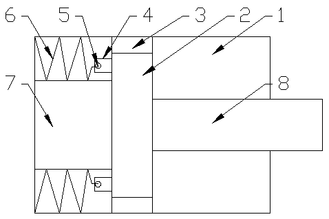
[0011] Such as figure 1 As shown, the present invention adopts a piston for engineering machinery, including a cylinder 1, a piston 2 is arranged in the cylinder 1, a piston rod 8 is arranged on one side of the piston 2, and a piston rod 8 is arranged on the other side of the piston 2. A gas filling chamber 7 is provided on the side, and it is characterized in that a connection block 4 is provided on the piston 2, and a through hole 5 is provided in the connection block 4, and the cylinder 1 is located on both sides of the gas filling chamber 7. A spring 6 is provided, a...


PUM


Abstract

The invention discloses a piston for engineering machinery. The piston comprises an air cylinder, a piston body is arranged in the air cylinder, a piston rod is arranged on one side of the piston body, and a gas filling cavity is formed in the other side of the piston body. The piston is characterized in that a connecting block is arranged on the piston body, through holes are formed in the connecting block, springs are arranged on two sides of the gas filling cavity in the air cylinder, and the other ends of the springs are located in the through holes; when the piston body and the piston rodretract, as gas in the gas filling cavity becomes less and less, the springs pull the piston body and the piston rod back as a result of inertia, so that the shrinking speed is accelerated, a lot oftime is saved and the work efficiency is improved.

Description

technical field [0001] The invention relates to a piston, in particular to a piston used in engineering machinery. Background technique [0002] Hydraulic cylinder is an important part of construction machinery. It is a hydraulic actuator that converts hydraulic energy into mechanical energy and performs linear reciprocating motion. Among them, piston hydraulic cylinder is the most common structure. It consists of a cylinder and a cylinder inside the cylinder. Composed of piston rod and piston. When the piston in the prior art is retracted, the speed is relatively slow, which wastes a lot of time and reduces work efficiency. Contents of the invention [0003] Aiming at the above-mentioned problems in the prior art, the present invention provides a piston for engineering machinery. When the piston and the piston rod need to be retracted, as the gas in the gas-filled chamber becomes less and less, the spring will push the piston back due to inertia. And the piston rod is p...

Claims


Application Information

Patent Timeline
IPC IPC(8): F15B15/14F15B15/22
Inventor 马娜王刚
Owner 江苏汉东机械有限公司
Why Eureka
Try Eureka