Overflow groove heating device and muffle furnace

A technology of heating device and overflow tank, which is applied in manufacturing tools, glass forming, glass manufacturing equipment, etc., can solve the problems of inability to guarantee the adjustment of plate thickness, inevitable deposition of precipitates, increase in production cost, etc., and achieve excellent edge. Plate thickness distribution, gain and dimensional stability, the effect of improving equipment life

Pending Publication Date: 2022-05-03
IRICO DISPLAY DEVICES
View PDF0 Cites 0 Cited by
  • Summary
  • Abstract
  • Description
  • Claims
  • Application Information

AI Technical Summary

Problems solved by technology

[0003] In the production process of the overflow down-draw method, it depends heavily on the precise control of the size of the overflow tank and the space temperature field in the production process. Larger, resulting in inevitable deposition of precipitates; at the same time, the flow state of the glass in the baffle area will change the flow state (due to the downward flow of the molten glass, the temperature of the surface of the molten glass decreases, and the molten glass receives surface tension, gravity, etc. and the infiltration of the baffle, the change of the flow state of the molten glass is also one of the main causes to induce precipitates), resulting in the change of the flow state in the baffle area, that is, in the baffle area over time, the glass liquid It is easy to produce some analytes to adhere to the baffle, further deteriorating the flow state
unfavorable to production
In the end, the adjustment of the plate thickness cannot be guaranteed, and the overall equipment life is shortened
Adverse effects that lead to a substantial increase in production costs

Method used


Image

  • Overflow groove heating device and muffle furnace
  • Overflow groove heating device and muffle furnace

Examples


Embodiment Construction

[0021] In order to enable those skilled in the art to better understand the solutions of the present invention, the technical solutions in the embodiments of the present invention will be clearly and completely described below in conjunction with the drawings in the embodiments of the present invention. Obviously, the described embodiments are only It is an embodiment of a part of the present invention, but not all embodiments. Based on the embodiments of the present invention, all other embodiments obtained by persons of ordinary skill in the art without making creative efforts shall fall within the protection scope of the present invention.

[0022] It should be noted that the terms "first" and "second" in the description and claims of the present invention and the above drawings are used to distinguish similar objects, but not necessarily used to describe a specific sequence or sequence. It is to be understood that the data so used are interchangeable under appropriate circ...


PUM


Abstract

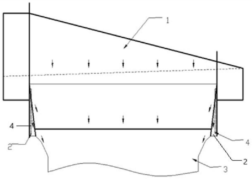
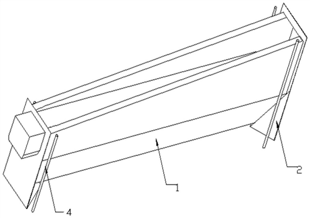
The invention provides an overflow groove heating device and a muffle furnace, which can ensure the uniformity and stability of a space temperature field, improve the production quality, prolong the service life of equipment and reduce the production cost. Comprising baffles arranged at the two ends of an overflow groove, the sides, making contact with molten glass flowing out of the overflow groove, of the baffles are arranged in a bent mode and used for changing the flowing direction of the molten glass, and a heater is installed on the other sides of the baffles; the heater is divided into an upper section and a lower section according to the position where the flowing direction of the molten glass changes, and the upper section and the lower section adopt heaters with different resistivity.

Description

technical field [0001] The invention relates to the technical field of flat glass production, in particular to an overflow tank heating device and a muffle furnace. Background technique [0002] With the increasing use of devices with various flat-panel display functions such as notebook computers and smartphones, the market demand for flat-panel substrate glass for manufacturing flat-panel displays has increased significantly. At the same time, due to the use of large-size flat panel displays, higher and higher requirements are put forward for parameters such as the size, flatness and internal stress of the flat substrate glass. Based on such a sharp increase in demand, the overflow down-draw method plays a pivotal role in the production of flat substrate glass. [0003] In the production process of the overflow down-draw method, it depends heavily on the precise control of the size of the overflow tank and the space temperature field in the production process. Larger, re...

Claims


Application Information

Patent Timeline
Patent Type & Authority Applications(China)
IPC IPC(8): C03B17/06
CPCC03B17/064
Inventor 李淼张栋张志军
Owner IRICO DISPLAY DEVICES
Why Eureka
Try Eureka