Ball mill filling rate measuring device

A measuring device and filling rate technology, applied in cleaning methods and utensils, chemical instruments and methods, level indicators of level members, etc., can solve the problem of extrusion damage of zero-degree positioning ruler and sheath, reduction of positioning effect of zero-point positioning ruler, The gap between the zero point positioning ruler and the sheath, etc., achieves the effect of increasing practicability, increasing cleaning effect, and high practicability

Pending Publication Date: 2022-06-07
青岛金星矿业股份有限公司
View PDF0 Cites 0 Cited by
  • Summary
  • Abstract
  • Description
  • Claims
  • Application Information

AI Technical Summary

Problems solved by technology

[0004] The technical problem to be solved by the present invention is that when the existing ball mill filling rate detection device is put away for use, air pressure will be generated between the two-point positioning ruler and the sheath. During the detection process, impurities are easily invaded inside the sheath. Therefore, when extruding, the impurities are squeezed between the zero positioning ruler and the sheath, which will damage the extrusion between the zero positioning ruler and the sheath, and will also cause a gap between the zero positioning ruler and the sheath. In the subsequent use, the positioning effect of the zero point positioning ruler is reduced, which in turn affects the detection of the filling rate

Method used


Image

  • Ball mill filling rate measuring device
  • Ball mill filling rate measuring device
  • Ball mill filling rate measuring device

Examples


Embodiment Construction

[0030] The following technical solutions of the present invention are further described in conjunction with the accompanying drawings and by specific embodiments.

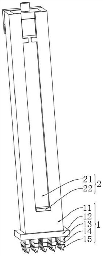
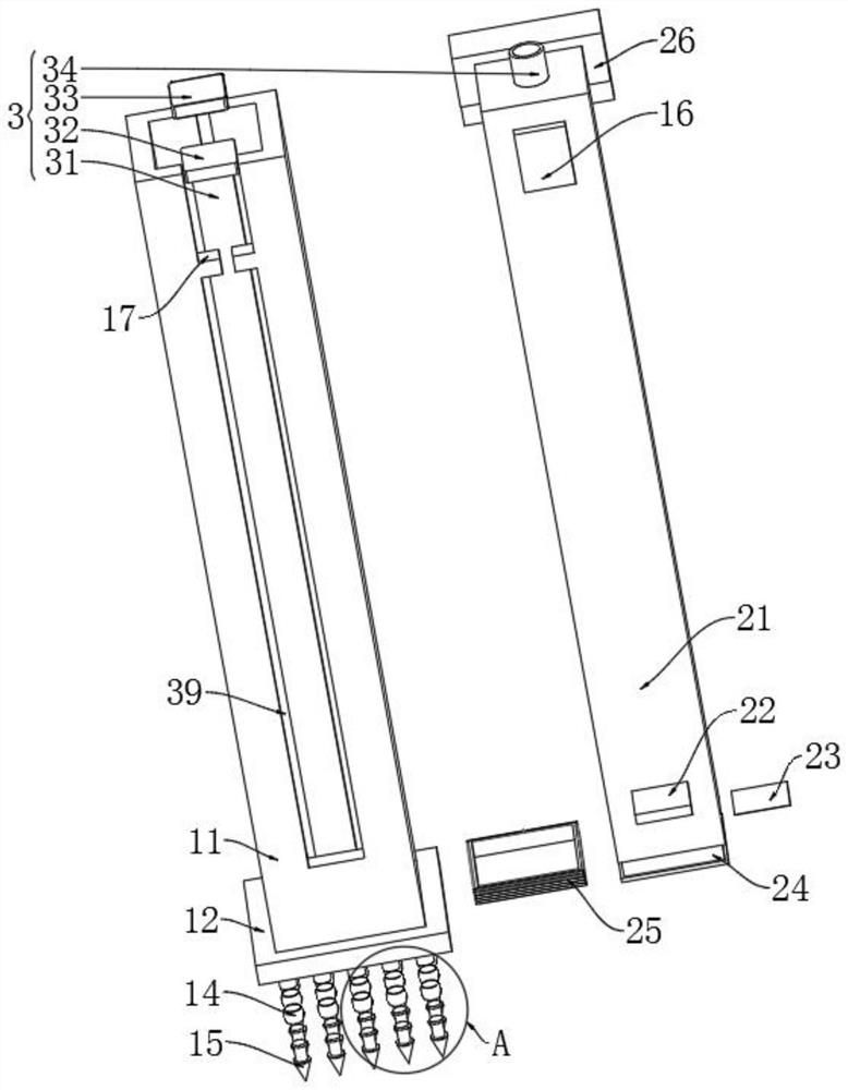
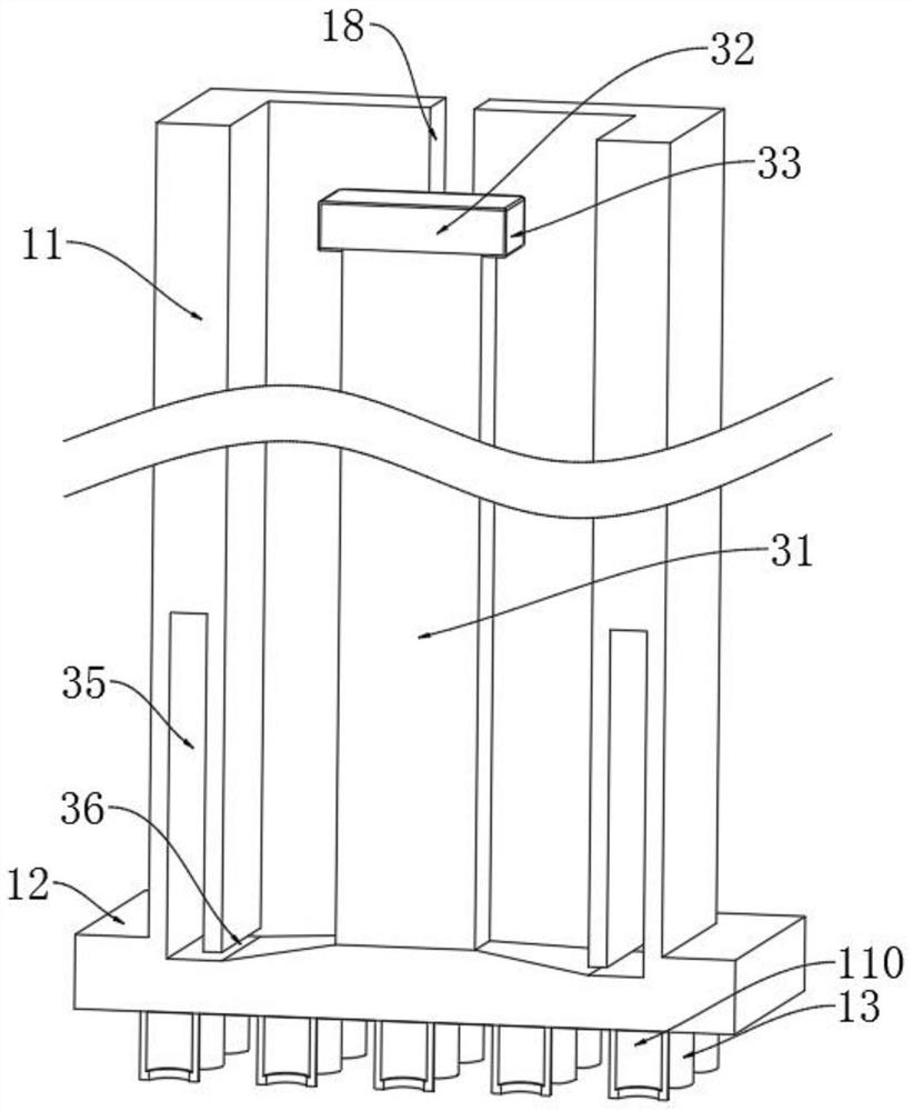
[0031] as Figure 1-5 As shown, the embodiment provides a ball mill filling rate measurement device, comprising a positioning detection structure 1, positioning detection structure 1 comprising a sliding sheath 11, the internal setting of the sliding sheath 11 is provided with a protective structure 2, the protective structure 2 includes a measuring slide ruler 21, the measuring slide ruler 21 sliding card is connected to the inside of the sliding sheath 11, the internal setting of the positioning detection structure 1 and the cleaning structure 3, the cleaning structure 3 includes the inner sliding card rod 31, the inner slip card rod 31 is fixed and connected to the middle of the sliding sheath 11, Measuring slide ruler 21 in the middle of the open inner sliding cavity 38, the inner slip card rod 31 sliding card is co...


PUM


Abstract

A ball mill filling rate measuring device disclosed by the present invention comprises a positioning detection structure, the positioning detection structure comprises a sliding sheath, the sliding sheath is internally provided with a protection structure, and the protection structure comprises a measuring slide scale. According to the ball mill filling rate measuring device, through the arrangement of an inner rotating air cavity and a connecting clamping rod, when a sliding sheath shrinks to the lower end of a front sliding clamping groove, air in the sliding sheath can be compressed through sealing between the lower end of a measuring sliding ruler and the interior of the sliding sheath, so that air flow enters the inner rotating air cavity from a bottom vent groove; and then the dust is sprayed out from the inclined air outlet, so that the dust at the lower end of the front sliding clamping groove is cleaned through blowing of the air flow, impurities are prevented from staying at the lower end of the front sliding clamping groove, and when the sliding sheath is completely contracted, the impurities are mixed between the front sliding clamping groove and the zero-point positioning rule, so that the zero-point positioning rule and the front sliding clamping groove are easily damaged.

Description

Technical field [0001] The present invention relates to the field of ball mills, and more particularly, to a ball mill filling rate measurement device. Background [0002] Ball mill is composed of horizontal cylinder, inlet and outlet hollow shaft and grinding head and other parts, the cylinder is a long cylinder, the cylinder is equipped with a grinding body, the cylinder is made of steel plate, there is a steel liner and the cylinder fixed, the grinding body is generally a steel ball, and according to different diameters and a certain proportion into the cylinder, the grinding body can also be used steel segments. According to the particle size of the grinding material to be selected, the material is loaded into the cylinder by the hollow shaft at the feeding end of the ball mill, when the ball mill cylinder rotates, the grinding body due to inertia and centrifugal force, the role of friction, so that it is attached to the cylinder liner to be taken away by the cylinder, when i...

Claims


Application Information

Patent Timeline
Patent Type & Authority Applications(China)
IPC IPC(8): G01F23/04B08B5/02B08B9/00
CPCG01F23/04B08B5/02B08B9/00
Inventor 高瑞琢孙松良许道学任兵张贵军刘月章周海涛张智斌崔浩楠吕旭君张天宾高文欣
Owner 青岛金星矿业股份有限公司
Why Eureka
Try Eureka