Handle device with a surface-flush handle

A handle, outer surface technology, applied in the field of moving parts, can solve problems such as loss

Inactive Publication Date: 2019-02-05
HUF HULSBECK & FURST GMBH & CO KG
View PDF4 Cites 2 Cited by
  • Summary
  • Abstract
  • Description
  • Claims
  • Application Information

AI Technical Summary

Problems solved by technology

However, the advantage of a flush

Method used


Image

  • Handle device with a surface-flush handle
  • Handle device with a surface-flush handle
  • Handle device with a surface-flush handle

Examples


Embodiment Construction

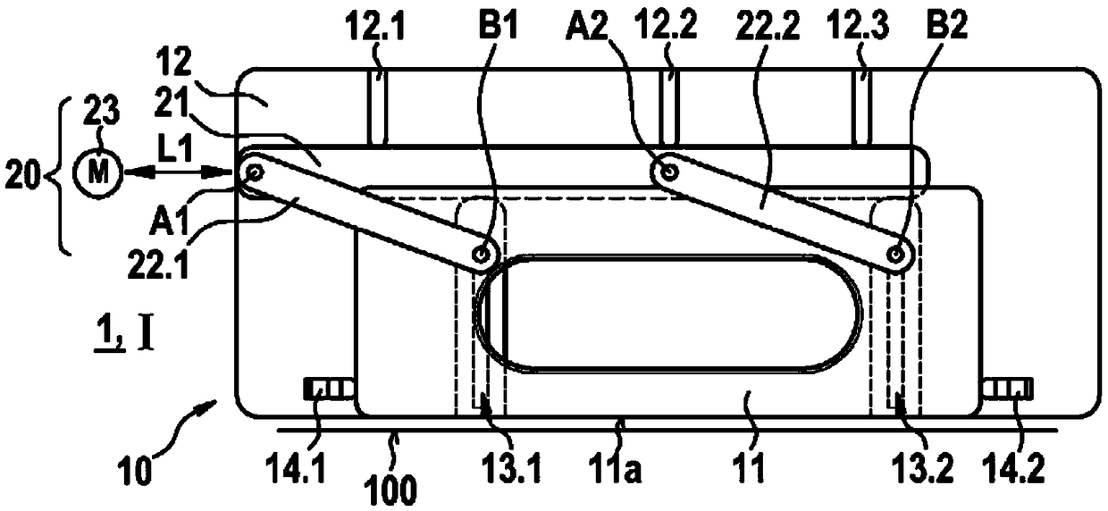
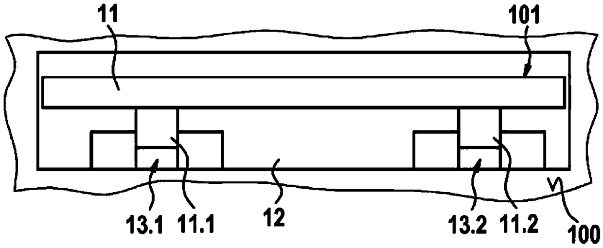
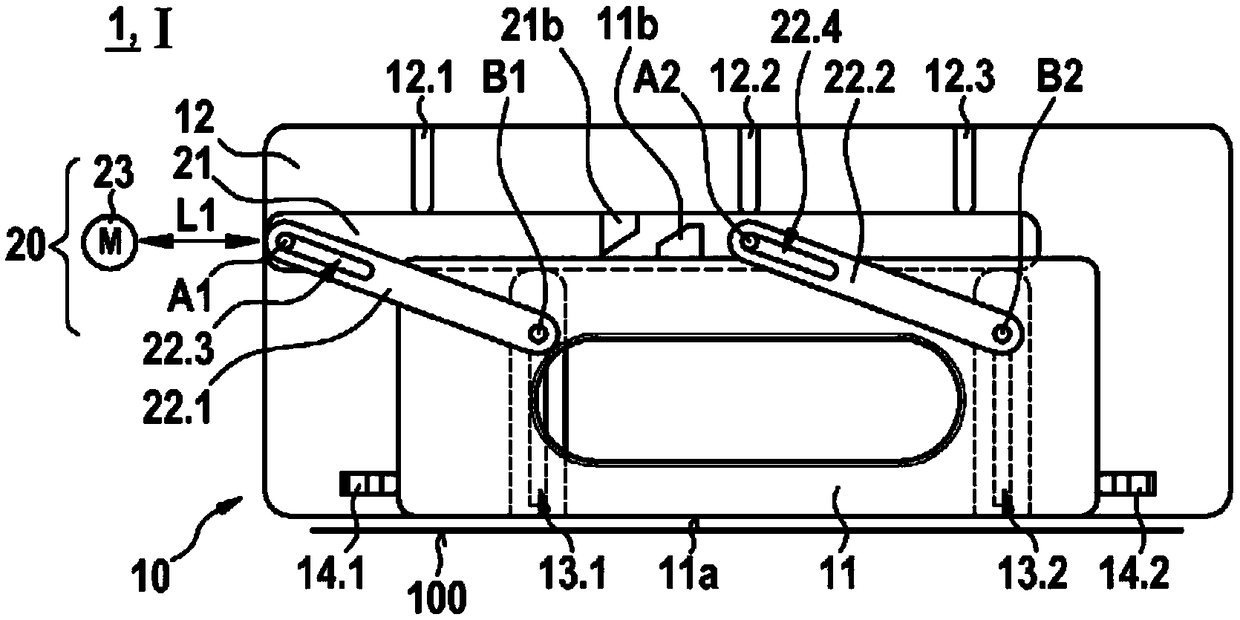
[0046] Figures 1a to 3The handle device 10 according to the invention is shown with a flush handle part 11 in the rest position I. Said handle part 11 is used according to the invention for operating, for example opening a movable part, such as a vehicle door. The handle arrangement 10 is fastened here to a bearing element 12 which can serve as a housing or frame structure for fixing the handle arrangement 10 to the movable part. In order to finally be able to operate the handle part 11, by means of the drive unit 20 it is possible to Figure 1a with Figure 2a shown in the surface-flush rest position I and in the Figure 2e with image 3 The handle part 11 is driven between the working position II shown in . as by Figure 1a As can be seen, the handle part 11 in the rest position I is arranged flush with the outer surface 11 a of the outer surface 100 of the movable part. exist Figure 2e with 3 In the working position II shown in , the handle part 11 is moved out of ...


PUM


Abstract

The invention relates to a handle device (10) for a movable part, in particular a door, of a motor vehicle, with a handle part (11) for actuating the movable part, with a carrier element (12) for fastening the handle device (10) on the movable part, wherein the handle part (11) is mounted on the carrier element (12) so as to be movable between a rest position (I) and an operating position (II), wherein the handle part (11) can be arranged in the rest position (I) with an outer surface (11a) surface-flush to an outer side (100) of the movable part, wherein, in the operating position (II), the handle part (11) can be moved out of an opening (101) in the outer side (100) of the movable part, and wherein, in the operating position (II), the handle part (11) can be operated to open the movablepart, and with a drive unit (20) for driving the handle part (11) between the rest position (I) and the operating position (II). For this purpose, there is provision according to the invention that the drive unit (20) is configured in such a way that the outer surface (11a) of the handle part (11) is movable between the rest position (I) and the operating position (II) of the handle part (11) always parallel to the outer side (100) of the movable part.

Description

technical field [0001] The invention relates to a handle arrangement for a movable part of a motor vehicle, in particular a door, according to the preamble of claim 1 . Here, the handle device is configured to have: a handle part for operating the movable part; Supported in motion between the bearing elements, the outer surface of the handle part can be arranged flush with the outer surface of the movable part in the rest position, and the handle part can be removed from the movable part in the working position. and the handle portion is operable in an operating position to open the movable part; and a drive unit for driving the handle portion between a rest position and an operating position. Background technique [0002] Handle devices with a flush handle part that can be moved between a retracted rest position and an extended working position are known in principle. However, the known handle devices have complex drive units for driving the handle parts, which require a ...

Claims


Application Information

Patent Timeline
IPC IPC(8): E05B85/10
CPCE05B81/04E05B85/103E05B85/107E05B81/76
Inventor 马提亚斯·洛威利·布特
Owner HUF HULSBECK & FURST GMBH & CO KG
Why Eureka
Try Eureka