Pressure regulator and fuel supply device

A pressure regulator and fuel technology, which is applied in fuel injection devices, low-pressure fuel injection, liquid fuel feeders, etc., can solve the problems that fuel pressure is difficult to change quickly, hinders responsiveness and pressure regulation accuracy, etc.

Active Publication Date: 2019-02-05
AISAN IND CO LTD
View PDF7 Cites 0 Cited by
  • Summary
  • Abstract
  • Description
  • Claims
  • Application Information

AI Technical Summary

Problems solved by technology

Therefore, even if the opening and closing states of the second pressure chamber and the third pressure chamber with respect to the fuel flow path are switched by the three-way valve, it is difficult for these respective pressure chambers to change quickly relative to the fuel pressure before switching, which hinders the response. Improvement of performance and pressure regulation accuracy

Method used


Image

  • Pressure regulator and fuel supply device
  • Pressure regulator and fuel supply device
  • Pressure regulator and fuel supply device

Examples


no. 1 approach

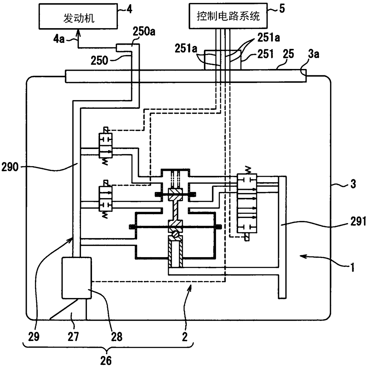
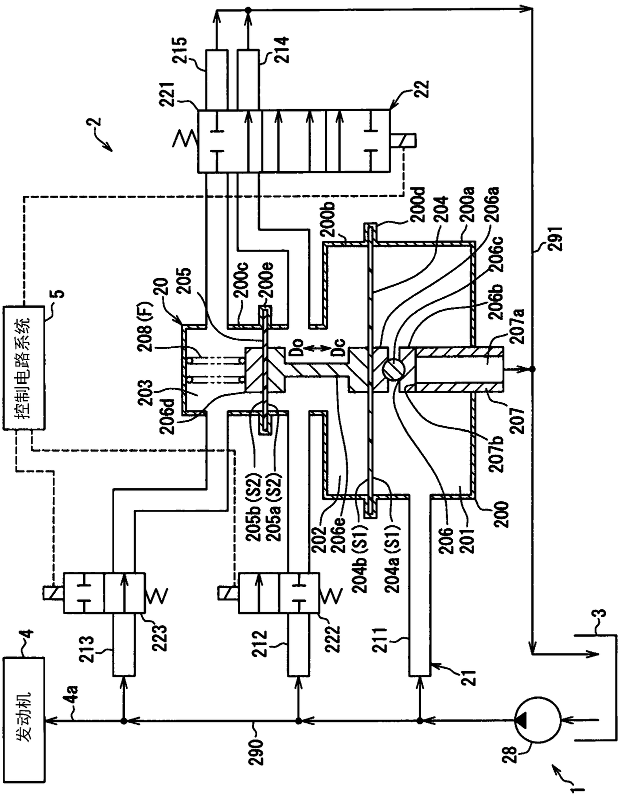
[0043] Such as figure 1 As shown, the fuel supply device 1 having the pressure regulator 2 according to the first embodiment of the present invention is applied to an internal combustion engine 4 of a vehicle by being mounted on a fuel tank 3 . The fuel supply device 1 supplies fuel stored in a fuel tank 3 in a vehicle to an internal combustion engine 4 outside the fuel tank 3 . Here, the insertion hole 3 a penetrates the upper wall of the fuel tank 3 . The fuel supply device 1 is inserted into the fuel tank 3 through the insertion hole 3a. In such an inserted state, the internal combustion engine 4 to be supplied with fuel from the fuel supply device 1 may be a gasoline engine or a diesel engine.

[0044] The fuel supply device 1 has a cover body 25 and a pump unit 26 . The lid body 25 is attached to the upper wall of the fuel tank 3 . By attaching in this way, the cover body 25 closes the insertion hole 3a. The cover body 25 has an integral fuel supply pipe 250 and an e...

no. 2 approach

[0104] Such as Figure 7 As shown, the second embodiment of the present invention is a modified example of the first embodiment.

[0105] The passage unit 2021 of the voltage regulator 2002 of the second embodiment does not form the second branch passage 212 . And correspondingly, the third release passage 2215 of the passage unit 2021 shares a common portion 2216 on the third pressure chamber 203 side with respect to the switching unit 2022 which will be described in detail later with the third branch passage 2213 . In addition, about the passage unit 2021, other parts are the same as those described in the first embodiment.

[0106] The switching unit 2022 of the voltage regulator 2002 of the second embodiment is composed only of the third solenoid valve 2223 , and the third solenoid valve 2223 is electrically connected to the control circuit system 5 through the terminal 251 a of the electrical connector 251 . The third solenoid valve 2223 is a three-port directional swit...

no. 3 approach

[0120] Such as Figure 11 As shown, the third embodiment of the present invention is a modified example of the first embodiment.

[0121] The passage unit 3021 of the voltage regulator 3002 of the third embodiment does not form the third branch passage 213 . And correspondingly, the second release passage 3214 of the passage unit 3021 shares a common portion 3216 on the second pressure chamber 202 side with respect to the switching unit 3022 which will be described in detail later with the second branch passage 3212 . In addition, about the passage unit 3021, other parts are the same as those described in the first embodiment.

[0122] The switching unit 3022 of the voltage regulator 3002 of the third embodiment is composed only of the second solenoid valve 3222 , and the second solenoid valve 3222 is electrically connected to the control circuit system 5 through the terminal 251 a of the electrical connector 251 . The second solenoid valve 3222 is a three-port directional s...


PUM


Abstract

Fuel diverted from a fuel circulation path flows into a first pressure chamber (201). A second pressure chamber (202) is adjacent to the first pressure chamber, and fuel diverted from the fuel circulation path flows into the second pressure chamber. A third pressure chamber (203) is adjacent to the second pressure chamber, and fuel diverted from the fuel circulation path flows into the third pressure chamber. A valve member (206) opens and closes the first pressure chamber with respect to a return path. A first partition member (204) operates in conjunction with the valve member in the state in which the first partition member partitions the first pressure chamber from the second pressure chamber. A second partition member (205) operates in conjunction with the valve member and the first partition member in the state in which the second partition member partitions the second pressure chamber from the third pressure chamber. A switch unit (22) performs switching between an open/close state of the second pressure chamber with respect to the fuel circulation path and an open/close state of the second pressure chamber with respect to the return path such that these open/close states are opposite to each other, and performs switching between an open/close state of the third pressure chamber with respect to the fuel circulation path and an open/close state of the third pressure chamber with respect to the return path such that these open/close states are opposite to each other.

Description

[0001] Cross References to Related Applications [0002] This application is based on Japanese Patent Application No. 2016-118359 filed on Jun. 14, 2016, and the content of the description is incorporated herein. technical field [0003] The present invention relates to a pressure regulator for adjusting fuel pressure in a fuel flow passage for directing fuel pumped by a fuel pump in a fuel tank toward an internal combustion engine side, and a fuel supply device including the pressure regulator. circulation. Background technique [0004] Conventionally, a pressure regulator that releases fuel from a fuel flow passage toward the internal combustion engine side into a fuel tank through a return passage to adjust the fuel pressure in the fuel flow passage has been widely used, for example, in fuel supply devices. As one type of such a pressure regulator, Patent Document 1 discloses a pressure regulator including a plurality of pressure chambers into which fuel branched from a ...

Claims


Application Information

Patent Timeline
Patent Type & Authority Applications(China)
IPC IPC(8): F02M37/00
CPCF02M37/0029F02M37/0052F02M37/10F02M69/54F02M37/00F02M63/005F02M63/023F02M63/0235
Inventor 林宣博
Owner AISAN IND CO LTD
Why Eureka
Try Eureka