
Clamp convenient to mount and dismount and used for conical surface turning of combined gear

A gear bevel and fixture technology, which is applied in the direction of manufacturing tools, metal processing equipment, metal processing machinery parts, etc., can solve the problems of low positioning accuracy, inconvenient precise loading and unloading, etc., and achieve the effect of reducing frictional resistance and contact area

Pending Publication Date: 2019-02-12
JIANGSU PACIFIC PRECISION FORGING +1
View PDF0 Cites 3 Cited by
  • Summary
  • Abstract
  • Description
  • Claims
  • Application Information

AI Technical Summary

Problems solved by technology

[0003] The purpose of the present invention is to solve the problem that the three-jaw centering chuck in the prior art is a universal fixture, which is cheap and easy to use, but has low positioning accuracy and is not convenient for precise loading and unloading, and proposes a combination gear for easy loading and unloading Fixtures for taper turning

Method used


Image

  • Clamp convenient to mount and dismount and used for conical surface turning of combined gear
  • Clamp convenient to mount and dismount and used for conical surface turning of combined gear
  • Clamp convenient to mount and dismount and used for conical surface turning of combined gear

Examples


Embodiment Construction

[0023] The following will clearly and completely describe the technical solutions in the embodiments of the present invention with reference to the accompanying drawings in the embodiments of the present invention. Obviously, the described embodiments are only some, not all, embodiments of the present invention.

[0024] In describing the present invention, it should be understood that the terms "upper", "lower", "front", "rear", "left", "right", "top", "bottom", "inner", " The orientation or positional relationship indicated by "outside", etc. is based on the orientation or positional relationship shown in the drawings, and is only for the convenience of describing the present invention and simplifying the description, rather than indicating or implying that the referred device or element must have a specific orientation, so as to Specific orientation configurations and operations, therefore, are not to be construed as limitations on the invention.

[0025] refer to Figure ...


PUM


Abstract

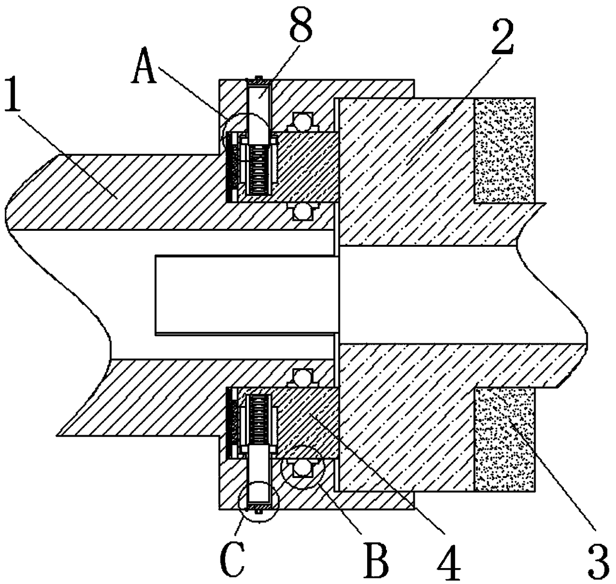
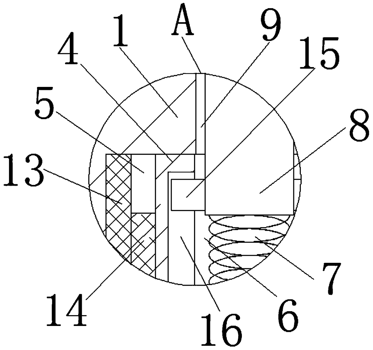
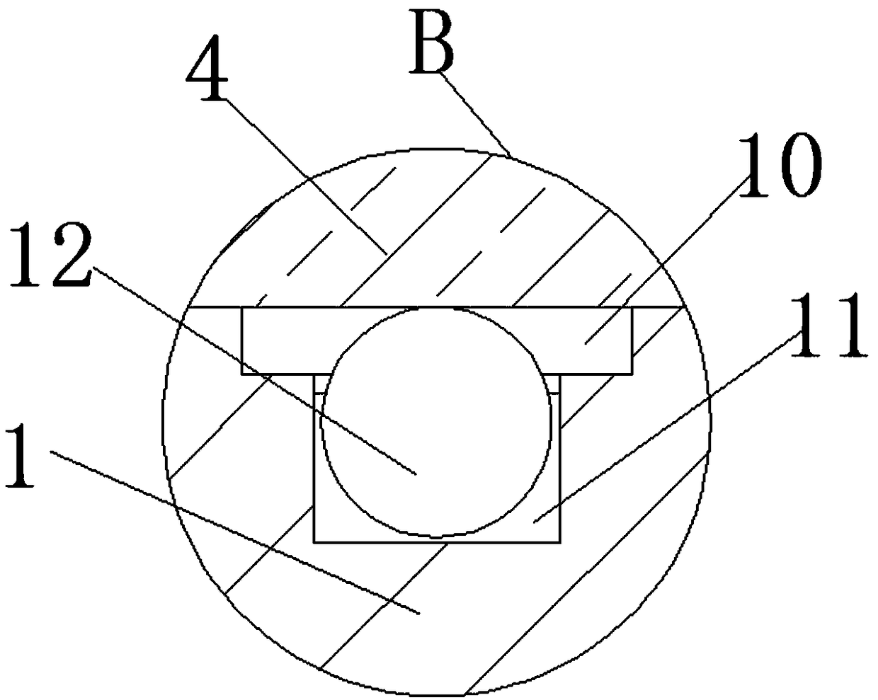
The invention discloses a clamp convenient to mount and dismount and used for conical surface turning of a combined gear. The clamp comprises a mandrel and a clamp body. The mandrel is of an externaltaper hollow shaft structure, and the clamp body is connected coaxially connected with the large end of the mandrel. A gasket is fixedly connected to the outer end surface of the clamp body. Fixing blocks are fixedly connected to the end, close to the mandrel, of the clamp body and symmetric with respect to the axis of the clamp body. Fixing grooves are formed in the positions, corresponding to the two fixing blocks, of the end, close to the clamp body, of the mandrel correspondingly. The ends, away from the clamp body, of the fixing blocks are inserted into the corresponding fixing grooves. Positioning grooves are formed in the positions, close to the groove bottoms of the fixing grooves, of the upper ends of the fixing blocks correspondingly. The groove bottoms of the positioning groovesare fixedly connected with springs correspondingly. The other ends of the springs are fixedly connected with positioning blocks correspondingly. Positioning holes are formed in the positions, corresponding to the positioning blocks, of the groove walls of the fixing grooves correspondingly. The ends, away from the springs, of the positioning blocks penetrate through groove openings of the positioning grooves and extend into the positioning holes correspondingly. By means of the clamp provided by the invention, the clamp body is mounted and dismounted precisely and conveniently.

Description

technical field [0001] The invention relates to the technical field of turning fixtures, in particular to a fixture that is convenient for loading and unloading and combined with gear bevel turning. Background technique [0002] Combining gears are helical spur gears used for torque transmission and speed change in automobile transmissions, and their manufacturing quality directly affects the balance of automobile transmission and gear shifting. The gear has a disc-shaped structure, one end of the gear axis is a tapered shaft, and the through hole in the middle is not only the design reference of the tapered shaft, but also the positioning reference. When machining combined gears, only the inner hole and one end face can be processed under one clamping condition, and the taper shaft at the other end needs to be repositioned for reprocessing. Due to the taper fit between the bevel shaft of the combined gear and the adjacent parts, the concentricity between the taper shaft an...

Claims


Application Information

Patent Timeline
Patent Type & Authority Applications(China)
IPC IPC(8): B23Q3/12
CPCB23Q3/12B23Q2703/10
Inventor 夏汉关董义赵红军王耀祖苟文星
Owner JIANGSU PACIFIC PRECISION FORGING
Learn More