New energy automobile charging gun
A new energy vehicle, charging gun technology, applied in electric vehicle charging technology, charging station, electric vehicle and other directions, can solve the problems of slow energy replenishment, damaged charging interface, long charging time, etc., and achieve the connection between the charging plug and the car Tighten, improve the service life, and facilitate the effect of daily use
- Summary
- Abstract
- Description
- Claims
- Application Information
AI Technical Summary
Problems solved by technology
Method used
Image

Examples
Embodiment 1
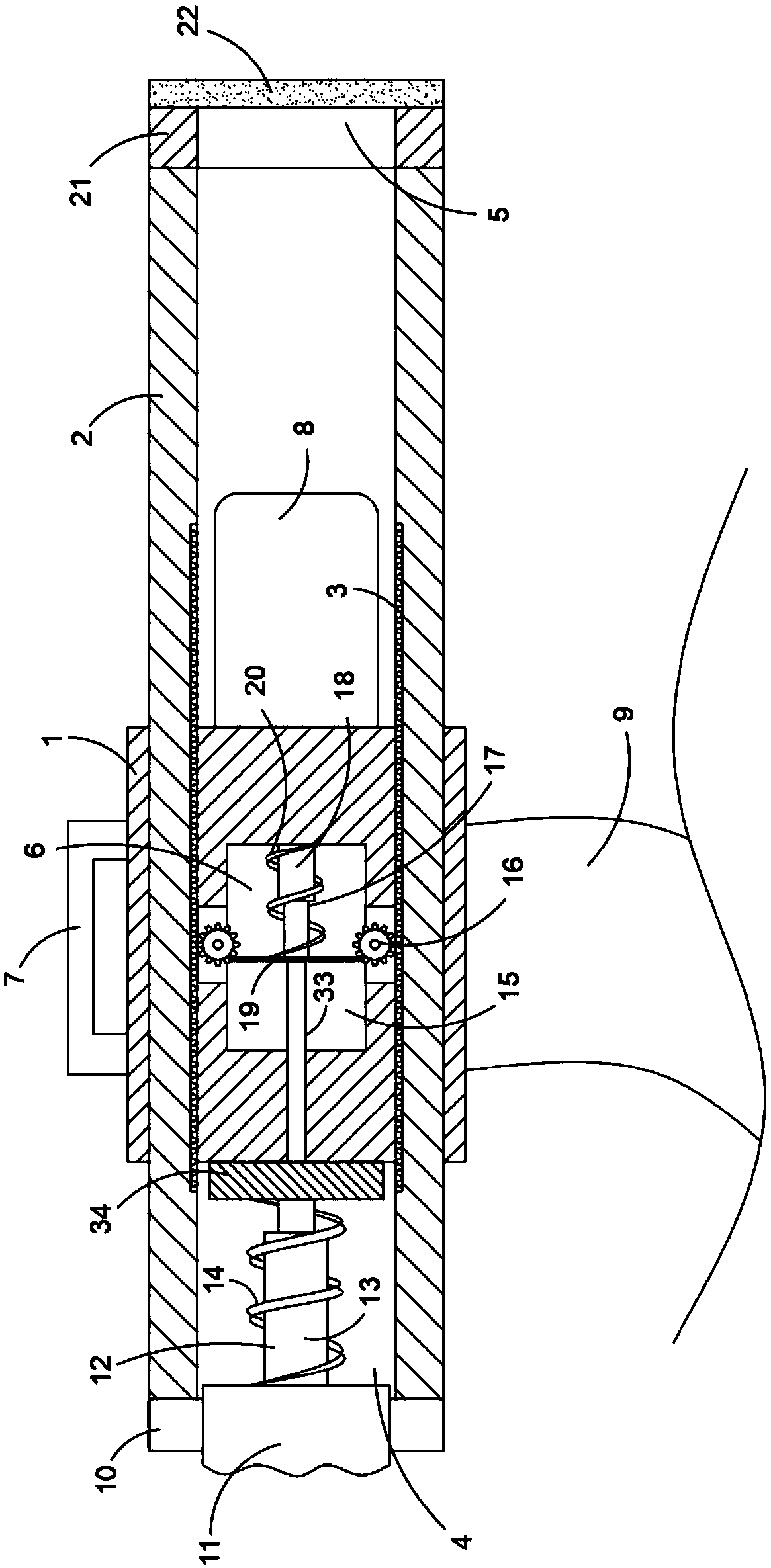
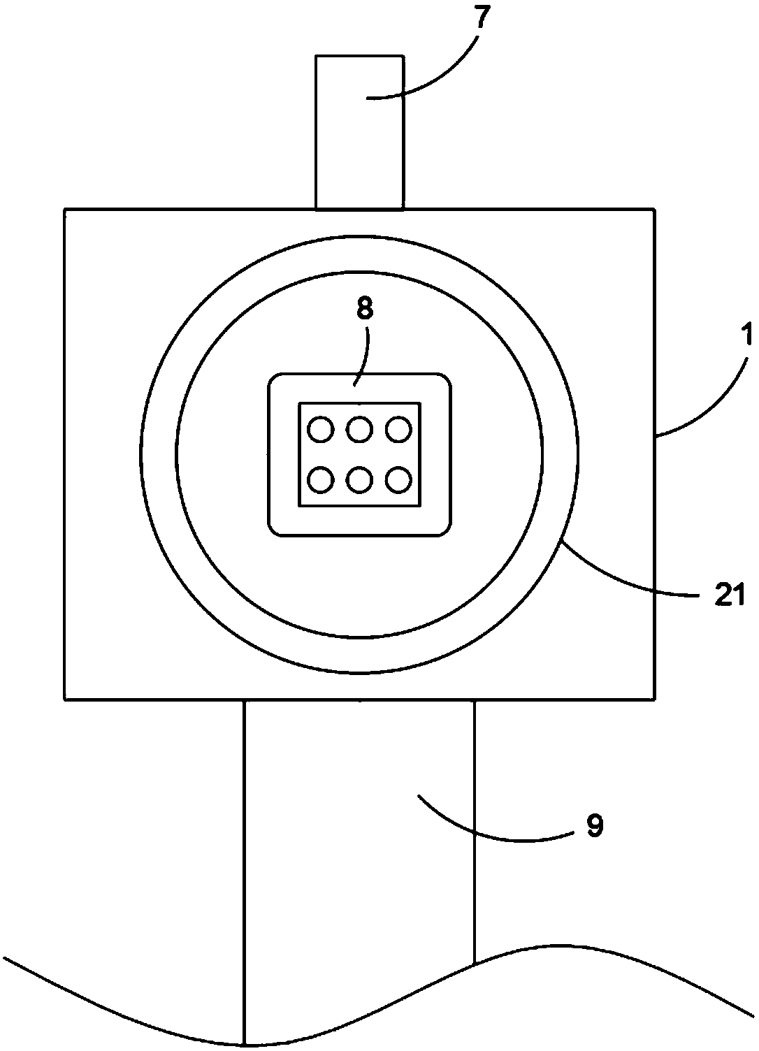
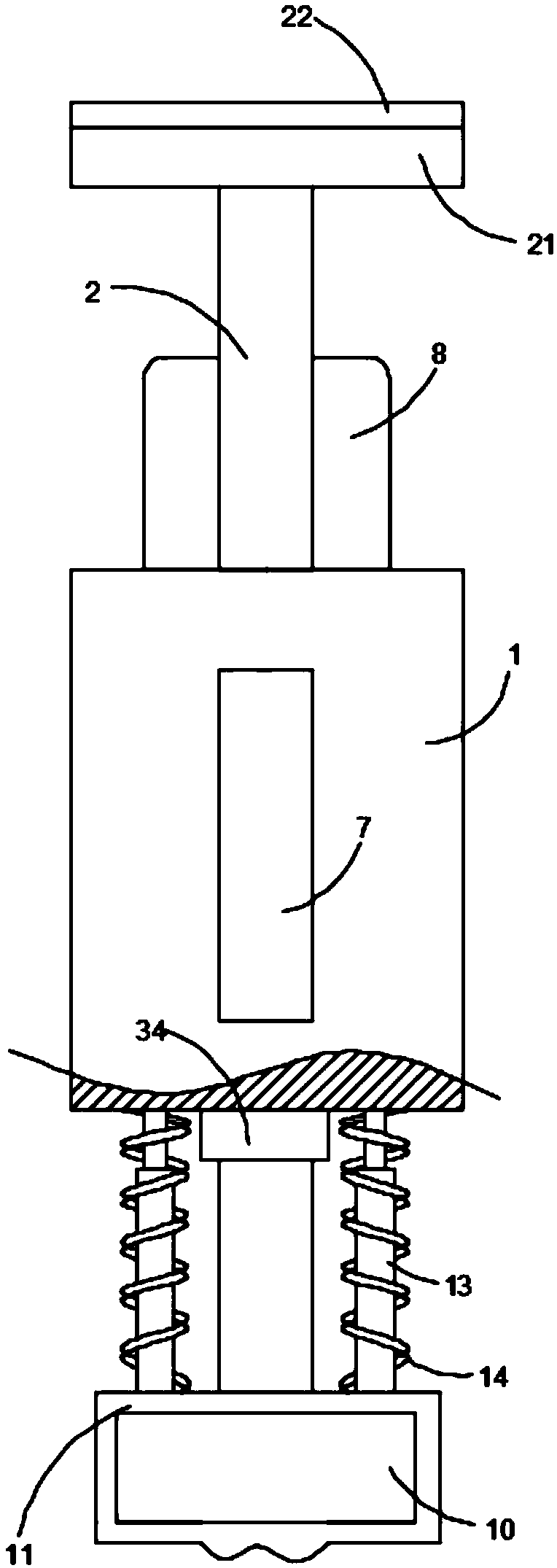
[0026] Such as Figure 1-3 As shown, a new energy vehicle charging gun includes a protective seat 1, and the protective seat 1 is inserted with two positioning rails 2 in the left and right directions. The positioning rails 2 and the protective seat 1 are movably connected. The side walls are fixedly connected with a first rack 3, and the left and right ends of the positioning rail 2 are respectively provided with a booster mechanism 4 and a fixing mechanism 5, and the booster mechanism 4 includes a connection vertically arranged on one side of the two positioning rails Plate 10, one end side wall of the connecting plate 10 is fixedly connected with the side walls of the two positioning rails 2, the connecting plate 10 is covered with a grip sleeve 11, and the grip sleeve 11 is an ergonomic curved shape, so that It is easier and more convenient for users to grasp.
[0027] A plurality of boosters 12 are fixedly connected to the side wall of the connecting plate 10 near the en...
Embodiment 2
[0033] refer to Figure 4-6 The difference between this embodiment and Embodiment 1 is that the fixing mechanism 5 includes a second chamber 23 arranged on the side wall of the positioning rail 2, the second chamber 23 is provided with a strip-shaped opening communicating up and down, and the second The top surface of the chamber 23 is provided with a chute 24, and the chute 24 is provided with a matching slider 25, the lower end of the slider 25 is fixedly connected with a second rack 26, and the lower end of the second rack 26 is fixedly connected There is a trigger plate 27, and the end of the trigger plate 27 away from the second rack 26 penetrates the bar-shaped opening and extends to the outside. Seat 1 provides cushioning, and second chamber 23 is provided with adsorption mechanism 36, and adsorption mechanism 36 is movably connected with second rack 26, and is fixedly connected with suction cup 28 on the side wall of positioning rail 2, and suction cup 28 is first conn...
PUM
 Abstract
Description
Claims
Application Information
 - R&D
- Intellectual Property
- Life Sciences
- Materials
- Tech Scout
- Unparalleled Data Quality
- Higher Quality Content
- 60% Fewer Hallucinations
Browse by: Latest US Patents, China's latest patents, Technical Efficacy Thesaurus, Application Domain, Technology Topic, Popular Technical Reports.
© 2025 PatSnap. All rights reserved.Legal|Privacy policy|Modern Slavery Act Transparency Statement|Sitemap|About US| Contact US: help@patsnap.com