
Heat transmission spiral heat dissipation handle

A heat transfer and handle technology, applied in the field of heat transfer spiral heat dissipation handle, can solve the problems of cyclist's hand slipping, handle falling off, cyclist's palm sweating, etc., to improve heat absorption and cooling efficiency, improve safety, and improve friction. The effect of resistance

Inactive Publication Date: 2019-02-12
王勇
View PDF9 Cites 6 Cited by
  • Summary
  • Abstract
  • Description
  • Claims
  • Application Information

AI Technical Summary

Problems solved by technology

In the process of riding a bicycle, the handle of the bicycle not only plays the role of correcting and controlling the riding direction, but also the braking devices of most existing bicycles adopt the hand-pinch brake installed on the handle. Therefore, the handle In the process of riding, it plays the role of controlling direction and braking at the same time, which has a great impact on riding safety.
[0003] The existing bicycle handles have poor heat dissipation effect. Since the rider must always hold the handle tightly, it often causes the palms of the rider to sweat. On the one hand, it will bring a poor riding experience. On the other hand, the existence of sweat, It is easy to cause the cyclist to slip and the handle is out of hand, especially when dealing with turning or complex road conditions, it is prone to accidents

Method used


Image

  • Heat transmission spiral heat dissipation handle
  • Heat transmission spiral heat dissipation handle
  • Heat transmission spiral heat dissipation handle

Examples


Embodiment 1

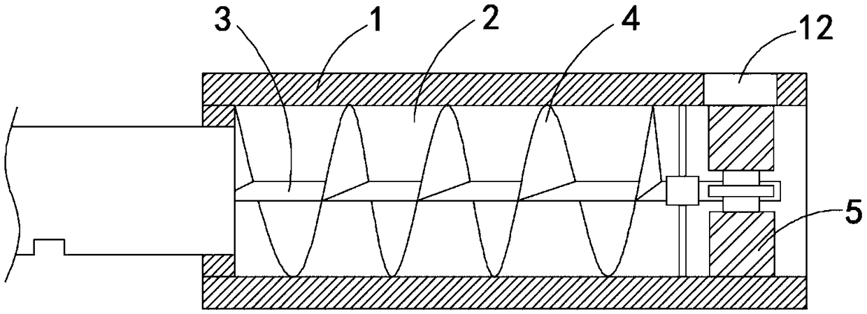
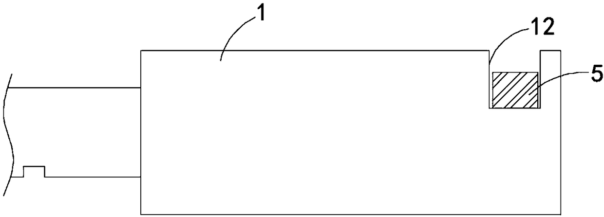
[0023] Such as Figure 1-2 As shown, a heat transfer spiral heat dissipation handle includes a handle body 1. The handle body 1 is made of a material with good thermal conductivity such as stainless steel to improve heat conduction efficiency. The rotating shaft 3 is connected in rotation, and a bearing is sleeved on the rotating shaft 3. The outer ring of the bearing is fixedly connected with the inner wall of the heat conducting chamber 2 through a plurality of connecting rods, and the rotating shaft 3 is rotationally connected with the inner wall of the heat conducting chamber 2 through the bearing. The helical blade 4 is fixedly connected, and the outer contour of the helical blade 4 is sealed and slid with the side wall of the heat conduction chamber 2 to ensure the one-way delivery of the airflow in the heat conduction chamber 2. One end of the rotating shaft 3 extends outside the heat conduction chamber 2 and is coaxial A plurality of fan blades 5 are fixedly connected,...

Embodiment 2

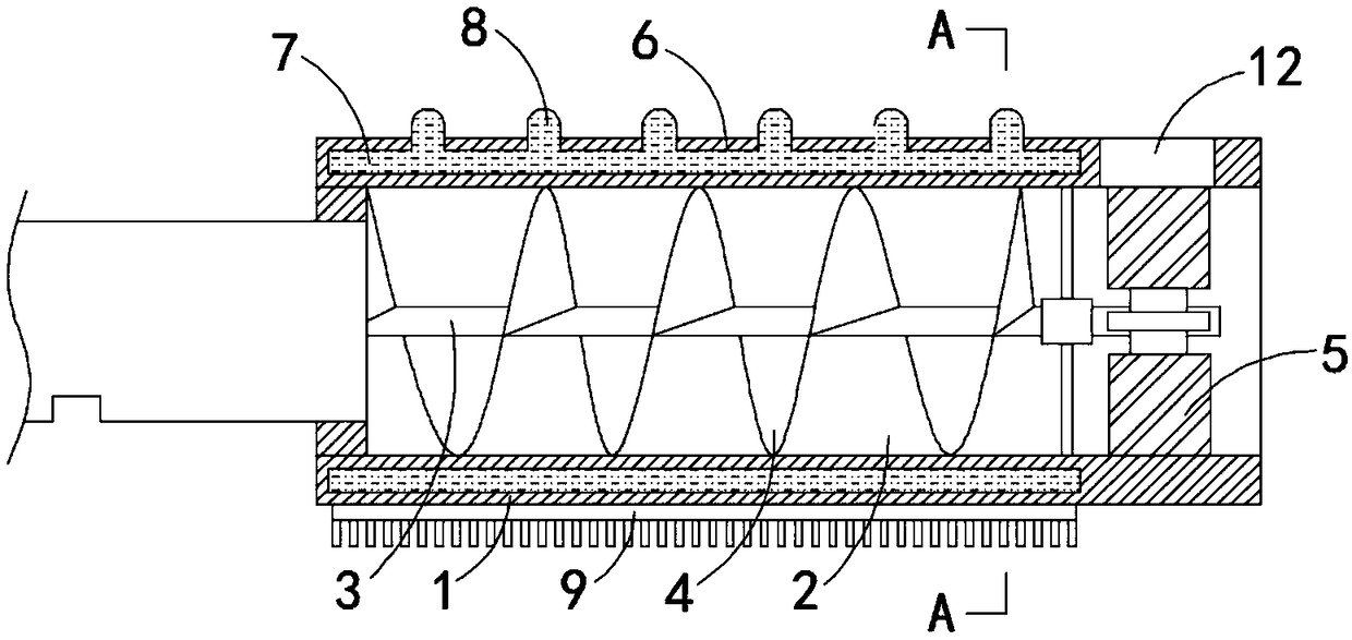
[0026] Such as Figure 3-5 As shown, the difference between this embodiment and Embodiment 1 is that: the handle body 1 is provided with an annular cavity 6, and the annular cavity 6 is filled with a cooling liquid 7, and the cooling liquid 7 can be water or has a larger specific heat capacity than water. The upper end of the handle body 1 is fixedly connected with a plurality of elastic liquid storage bags 8, the elastic liquid storage bags 8 can be made of materials such as silica gel or rubber, and the elastic liquid storage bags 8 are arc-shaped, which is easy to hold, and the elastic liquid storage bags 8 Connected with the annular cavity 6, the lower end of the handle body 1 is fixedly connected with a cooling fin 9, and the lower surface of the cooling fin 9 is fixedly connected with a plurality of cooling fins, and the extending direction of the cooling groove formed between adjacent cooling fins is the same as The riding direction is parallel, so that the wind can qui...


PUM


Abstract

The invention belongs to the field of bicycle accessories, and particularly relates to a heat transmission spiral heat dissipation handle. The heat transmission spiral heat dissipation handle comprises a handle body, wherein heat conduction cavities are formed in the handle body; a rotating shaft is rotatably connected in the heat conduction cavities; spiral blades are fixedly connected to the rotating shaft; the spiral blades are hermetically connected with the side walls of the heat conduction cavities; one end of the rotating shaft extends out of the heat conduction cavities and is coaxially and fixedly connected with a plurality of fan blades; and grooves corresponding to the fan blades are formed in the side wall of the handle body. According to the heat transmission spiral heat dissipation handle, by arranging the spiral blades and the fan blades, during riding, the fan blades are driven to rotate under the action of wind force, and the fan blades drive the spiral blades to rotate through the rotating shaft, so that the hot air flow in the heat conduction cavities is continuously transmitted to the outside, the heat in the heat conduction cavities is taken away, the cooling effect is achieved, the situation that hands slip off due to more sweat in palms of a rider is avoided, and the safety in the riding process is improved.

Description

technical field [0001] The invention belongs to the field of bicycle accessories, in particular to a heat-transmitting spiral cooling handle. Background technique [0002] As the former kingdom of bicycles, bicycles are becoming popular again when the era of shared bicycles comes. In the process of riding a bicycle, the handle of the bicycle not only plays the role of correcting and controlling the riding direction, but also the braking devices of most existing bicycles adopt the hand-pinch brake installed on the handle. Therefore, the handle In the process of riding, it plays the role of controlling direction and braking at the same time, which has a great impact on riding safety. [0003] The existing bicycle handles have poor heat dissipation effect. Since the rider must always hold the handle tightly, it often causes the palms of the rider to sweat. On the one hand, it will bring a poor riding experience. On the other hand, the existence of sweat, It is easy to cause t...

Claims


Application Information

Patent Timeline
IPC IPC(8): B62K21/26B62J33/00B62J6/00
CPCB62J6/01B62J33/00B62K21/26
Inventor 王勇
Owner 王勇
Learn More