Large-angle turning device of belt conveyor

A technology of belt conveyor and turning device, which is used in transportation and packaging, conveyors, conveyor objects, etc., can solve problems such as heat damage, material throwing, and inability to achieve

Inactive Publication Date: 2019-02-12
安徽省皖矿机电装备有限公司
View PDF0 Cites 0 Cited by
  • Summary
  • Abstract
  • Description
  • Claims
  • Application Information

AI Technical Summary

Problems solved by technology

[0003] However, the existing turning device only considers how to correct the deviation, but does not design from the root of the turning. Therefore, in the turning of the belt conveyor, the power of the transmission motor is increased or the heat is damaged, the belt is deviated, the edge is torn, and the throwing What's more, these turning devices can only realize the turning of no more than 25 degrees. For more than 25 degrees, it can't be realized at all. It is necessary to design a turning device that can better complete the belt turning.

Method used


Image

  • Large-angle turning device of belt conveyor

Examples


Embodiment 1

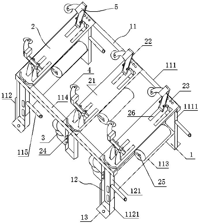
[0019] Such as figure 1 As shown, a large-angle turning device of a belt conveyor is composed of a plurality of turning units. The turning unit includes an underframe mechanism 1 and an idler mechanism 2. The underframe mechanism 1 includes a base frame 11 and an adjustment frame. 12. The adjustment frame 12 is installed on one side of the base frame 11; the roller mechanism 2 includes an end face mounting frame 21, one end of the end face mounting frame 21 is installed on the uppermost end surface of the base frame 11, and the other end is installed on the adjustment frame 12 On the uppermost end face, adjustment units are arranged on the corresponding installation surfaces of the roller mechanism 2, the base frame 11, and the adjustment frame 12; the roller mechanism 2 also includes a side roller frame 22 and a main roller frame 25, two The side roller frames 22 are respectively installed on both sides of the end surface mounting frame 21 close to the base frame 11 and the a...

Embodiment 2

[0024] As an optimized design for Example 1, the base frame 11 at least includes a height-fixing frame 111 on one side, an adjustment mounting frame 112 on the other side, and several connecting rods 113 connecting the height-fixing frame 111 and the adjustment mounting frame 112 .

[0025] The height-fixing frame 111 is composed of at least two height-fixing legs 1111, the end beams 114 connecting the two height-fixing legs 1111, the fixed plate 13 arranged on the lower end surface of the height-fixing legs 1111, and the return idlers installed on the height-fixing legs 1111 A set of mounting rods 115; the adjustment mounting frame 112 includes at least two slot legs 1121, and the fixing plate 13 is installed on the lower end surface of the slot legs 1121; the connecting rod 113 connects the height-fixing legs 1111 and the slot legs 1121.

[0026] The adjustment frame 12 includes two adjustment slot legs 121, the end beam 114 connecting the two adjustment slot legs 121, and t...

Embodiment 3

[0028] As an optimized design for Example 1, the side roller frame 22 includes a pair of side roller fixing ear frames and a side roller fixing frame, and several installation holes are arranged on the two side roller fixing ear frames, The fixed frame of the side roller is fixed through the mounting holes, and the angle with the end mounting frame is adjusted through different mounting holes.

[0029] An arc-shaped upper limit adjustment frame is installed on the side idler frame 22, and an adjustment wheel is installed on the upper limit adjustment frame.

[0030] After the position between the two side roller frames is adjusted, it is sometimes necessary to adjust the angle of the side rollers. Therefore, a side roller fixing ear frame with several mounting holes is designed to realize the angle adjustment of the side roller fixing frame.


PUM


Abstract

The invention discloses a large-angle turning device of a belt conveyor. The device is formed by combining a plurality of turning units; each turning unit comprises a bottom frame mechanism and a carrier roller mechanism, the bottom frame mechanism comprises a base frame and an adjusting frame, the adjusting frame is arranged on one side of the base frame, the carrier roller mechanism comprises anend surface mounting frame, side carrier roller frames and a main carrier roller frame, one end of the end surface mounting frame is arranged on the uppermost end surface of the base frame, the otherend of the end surface mounting frame is arranged on the uppermost end surface of the adjusting frame, the corresponding mounting surfaces of the carrier roller mechanism, the base frame and the adjusting frame are each provided with an adjusting unit; every two side carrier roller frames are arranged on the two sides, close to the corresponding base frame and the corresponding adjusting frame respectively, of each end surface mounting frame, and adjusting grooves are formed in the corresponding mounting positions, two side carrier rollers are arranged on the corresponding side carrier rollerframes, and the main carrier roller frame is arranged on a middle frame of the corresponding end surface mounting frame. According to the device, through the adjustments of the bottom frame mechanismand the carrier roller mechanism of each turning unit and the side carrier roller frames, the maximum 45-degree angle and resistance-free turning can be realized, material fling is avoided, deviationis avoided, and the device is suitable for turning in any direction.

Description

technical field [0001] The invention relates to a belt conveyor, in particular to a large-angle turning device for a belt conveyor. Background technique [0002] The belt conveyor is a machine that uses the infinite motion of the belt to transport materials. In many cases, the belt needs to turn, but the structure of the belt conveyor limits its turning ability. In order to make it turn, it is necessary to install a turning device in the structure of the belt conveyor. The performance inspection standard, the normal turning here includes: 1. Turning without resistance can be realized without throwing materials; 2. There will be no accidents such as belt deviation and belt tearing or falling off; 3. Adapt to turning in any direction, one machine adjustable. [0003] However, the existing turning device only considers how to correct the deviation, but does not design from the root of the turning. Therefore, in the turning of the belt conveyor, the power of the transmission m...

Claims


Application Information

Patent Timeline
Patent Type & Authority Applications(China)
IPC IPC(8): B65G41/00B65G21/14B65G15/64B65G21/20B65G39/16
CPCB65G41/003B65G15/64B65G21/14B65G21/20B65G39/16
Inventor 张孝郎
Owner 安徽省皖矿机电装备有限公司
Why Eureka
Try Eureka