
Unmanned aerial vehicle mounting device for automatic blade tracking detection, unmanned aerial vehicle and method

An automatic tracking and detection method technology, applied in the direction of measuring devices, equipment for loading and unloading cargo, aircraft parts, etc., can solve problems such as errors, inability to guarantee the center of the picture taken by fan blades, GPS positioning errors, etc., and achieve easy detection Effect

Inactive Publication Date: 2019-01-04
SHANGHAI CLOBOTICS TECHNOLOGY CO LTD
View PDF7 Cites 3 Cited by
  • Summary
  • Abstract
  • Description
  • Claims
  • Application Information

AI Technical Summary

Problems solved by technology

However, when the drone is loaded with a camera for work, GPS is used for positioning, but there are errors in GPS positioning and certain errors when modeling the flight path of the drone. There is a situation where it deviates from the shooting screen, so it is necessary to keep tracking the leaves

Method used


Image

  • Unmanned aerial vehicle mounting device for automatic blade tracking detection, unmanned aerial vehicle and method
  • Unmanned aerial vehicle mounting device for automatic blade tracking detection, unmanned aerial vehicle and method
  • Unmanned aerial vehicle mounting device for automatic blade tracking detection, unmanned aerial vehicle and method

Examples


Embodiment Construction

[0065] The present invention will be described in detail below in conjunction with specific embodiments. The following examples will help those skilled in the art to further understand the present invention, but do not limit the present invention in any form. It should be noted that those skilled in the art can make several modifications and improvements without departing from the concept of the present invention. These all belong to the protection scope of the present invention.

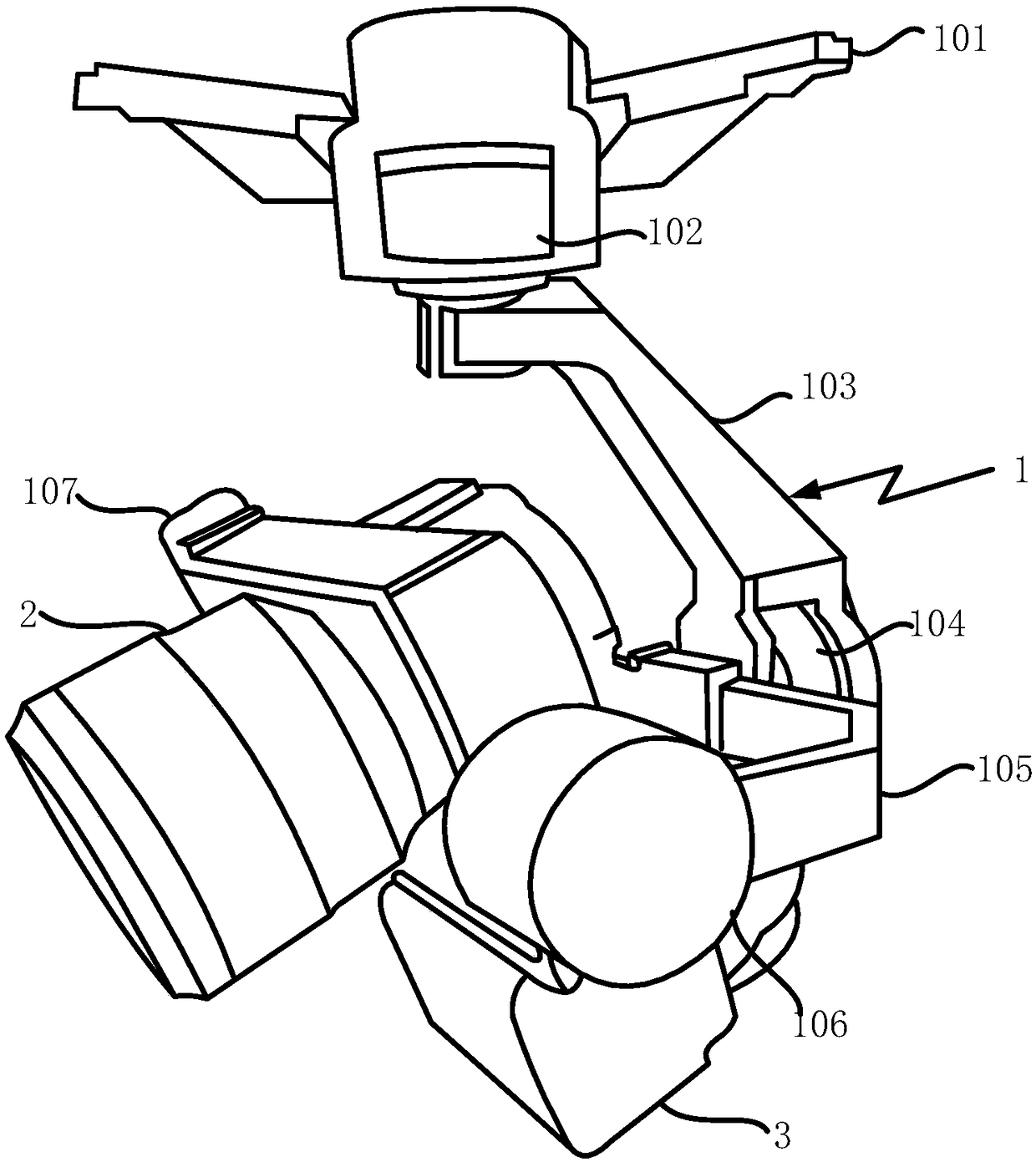
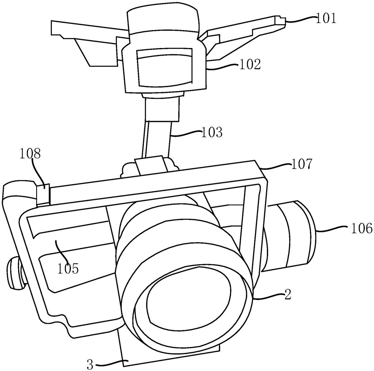
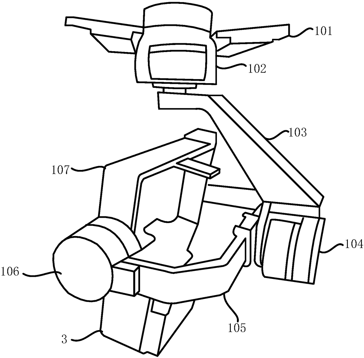
[0066] figure 1 , figure 2 A schematic structural view of the UAV mounting device used for blade automatic tracking and detection in the present invention is shown, as figure 1 , figure 2 As shown, the present invention provides a UAV mounting device for automatic blade tracking and detection, including a gimbal 1, a camera 2 and a solid-state radar 3;

[0067] The front end of described cloud platform 1 is provided with a mounting platform 107; Described cloud platform 1 drives described mou...


PUM


Abstract

The invention provides an umanned aerial vehicle mounting device for automatic blade tracking detection, an unmanned aerial vehicle and a method, which are used for automatic blade tracking detection,comprising a head, a camera and a solid-state radar. The front end of the pan platform is provided with a mounting platform; the pan table drives the mounting table to rotate in a first direction; One side of the mounting table is provided with the camera, and the other side is provided with the solid-state radar; the lens orientation of the camera is the same as the detection port orientation ofthe solid-state radar. As that solid-state radar and the camera are arrange on the same mounting table, the angle can be adjusted simultaneously with the rotation of the mounting table so as to ensure that when the solid-state radar detects a blade area of the target blade, the blade area is simultaneously within the shooting field of the camera, thereby facilitating detection of the tracked target blade.

Description

technical field [0001] The invention relates to fan blade tracking detection, in particular to a drone mounting device, drone and method for automatic blade tracking detection. Background technique [0002] A wind turbine is a power device that converts wind energy into mechanical work, which drives the rotor to rotate, and finally outputs alternating current. Wind turbines generally consist of components such as blades, generators, steering devices, towers, speed limiting safety mechanisms, and energy storage devices. [0003] During the long-term operation of the wind turbine, the surface of the blade will show various damages, such as damage to the protective film of the blade, peeling of the paint on the blade, freezing of the blade, cracks on the blade, and oil pollution on the blade. [0004] At present, when detecting damage on the surface of the blade, it is usually used to manually climb up the wind turbine for detection, which not only consumes a lot of manpower, ...

Claims


Application Information

Patent Timeline
IPC IPC(8): B64D9/00B64D47/00B64D47/08G01S13/66G01S13/89
CPCB64D9/00B64D47/00B64D47/08G01S13/66G01S13/89
Inventor 卢原王海洋柯亮苏航
Owner SHANGHAI CLOBOTICS TECHNOLOGY CO LTD
Learn More