Optical module

An optical module and optical port technology, applied in the field of optical modules, can solve the problems of the negative impact of optical modules, electromagnetic interference, and the inability to fully guarantee the absorption of electromagnetic waves, and achieve the effect of optimizing EMI performance and shielding radiant energy.

Inactive Publication Date: 2019-02-12
HISENSE BROADBAND MULTIMEDIA TECH
View PDF2 Cites 2 Cited by
  • Summary
  • Abstract
  • Description
  • Claims
  • Application Information

AI Technical Summary

Problems solved by technology

[0004] However, in specific operation and use, when the electromagnetic wave radiation is too strong, the absorbing material surrounding the electronic components cannot completely guarantee the absorption of the electromagnetic wave generated by it, for example, the electromagnetic wave penetrates the absorbing material and radiates into the cavity of the optical module
However, due to the surface process requirements and structural design requirements of the upper cover 1 and the base 2, there is a gap between the emitting light port 4 and the receiving light port 5 and the upper cover 1 and the base 2, and the electromagnetic waves radiated into the cavity of the optical module pass through the emitting light port 4 and the gap between the receiving optical port 5 and the upper cover 1 and the base 2 radiate out, causing electromagnetic interference to the outside world, which will cause a negative impact on the optical module

Method used


Image

  • Optical module
  • Optical module
  • Optical module

Examples


Embodiment 1

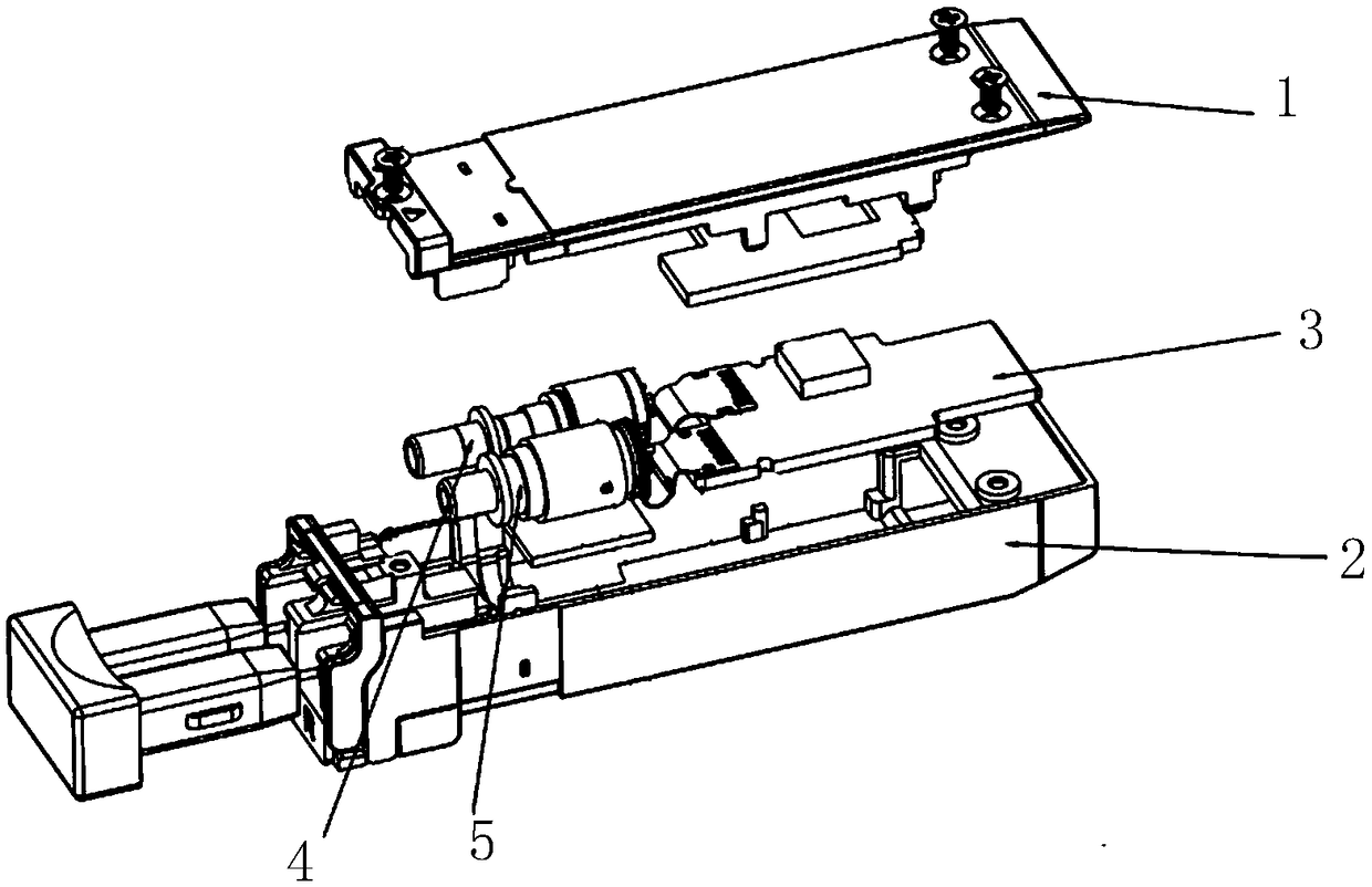
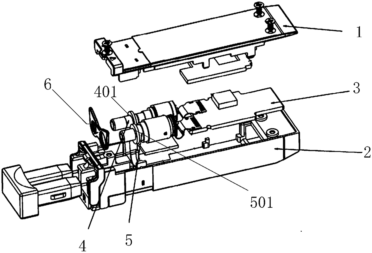
[0027] In order to solve the deficiencies in the above technical solutions, an embodiment of the present application provides an optical module. as attached figure 2 with 3 As shown, the optical module provided by the embodiment of the present application includes an upper cover 1 , a base 2 , a circuit board 3 , a light emitting port 4 , a light receiving port 5 and a wave absorbing gasket 6 . in:

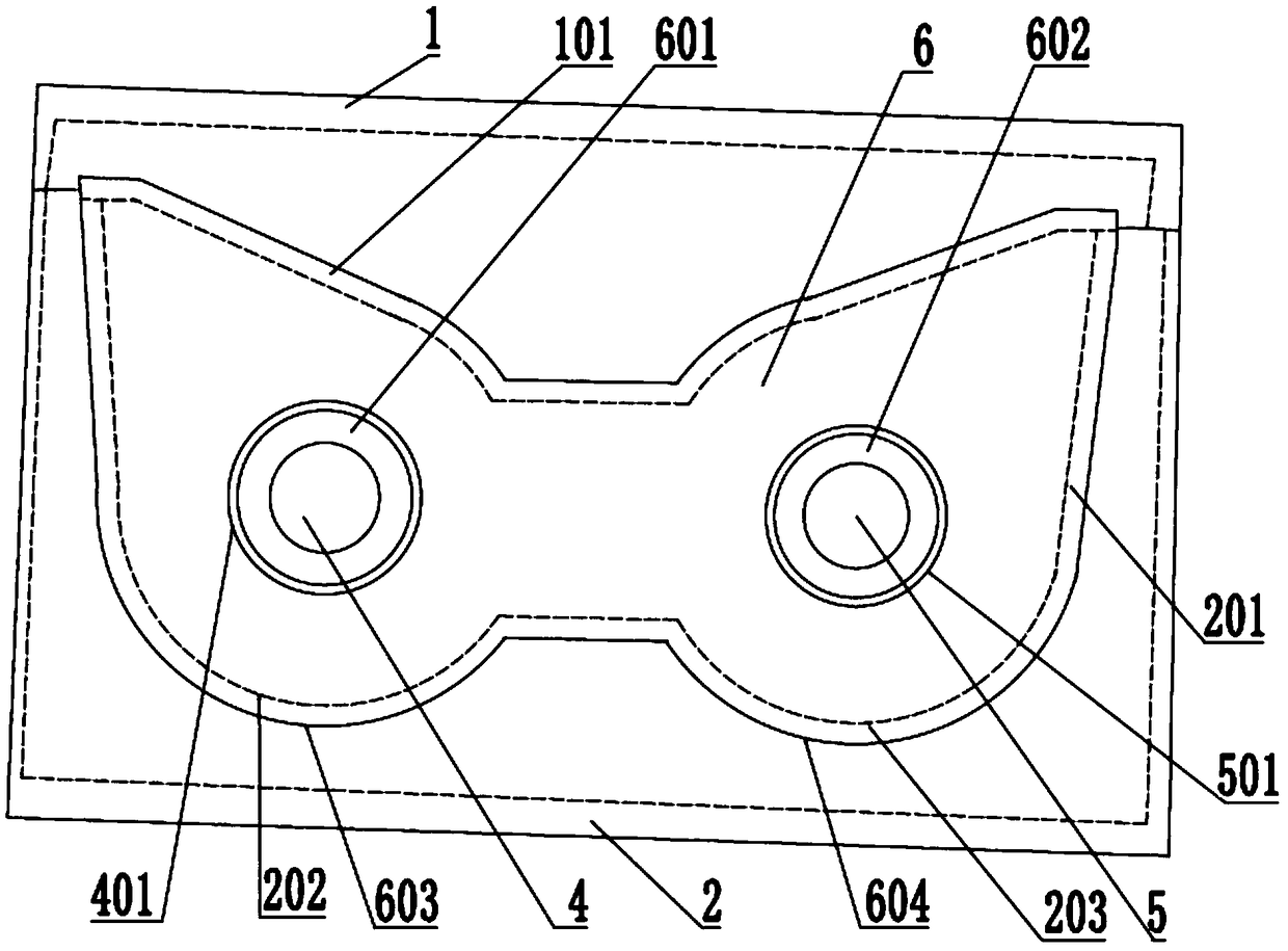
[0028] attached image 3 to follow figure 2 A cross-sectional view of the middle wave-absorbing gasket 6 in the longitudinal section direction. as attached image 3 As shown, the inner side of the upper cover 1 is provided with a first card slot 101, the distance between the middle part of the first card slot 101 and the bottom surface of the upper cover 1 is higher than the distance between the two ends of the first card slot 101 and the bottom surface of the upper cover 1, and the inner side of the base 2 The second card slot 201 is provided, and the absorbing gasket 6 i...

Embodiment 2

[0046] In order to solve the deficiencies in the above technical solutions, based on the same inventive concept, an embodiment of the present application further provides an optical module. The optical module includes a top cover, a base, a light emitting port, a light receiving port and a wave-absorbing pad, the inside of the top cover is provided with a first card slot, and the inside of the base is provided with a second card slot; the middle part of the first card slot and the The distance between the bottom surface of the upper cover is lower than the distance between the two ends of the first card slot and the bottom surface of the upper cover; the absorbing gasket is provided with a first through hole and a second through hole, and the emitting light port is penetrated through the first through hole, and the receiving The optical port is set in the second through hole; the upper edge of the wave-absorbing pad is set in the first slot, the lower edge of the wave-absorbing...


PUM


Abstract

The invention provides an optical module. The optical module comprises an upper cover, a base, a transmitting optical port and a receiving optical port, wherein a first clamping groove is formed in the inner side of the upper cover, and a second clamping groove is formed in the inner side of the base; the distance between the middle pat of the first clamping groove and the bottom surface of the upper cover is higher than the distances between two ends of the first clamping groove and the bottom surface of the upper cover. The optical module also comprises a microwave absorption gasket, whereina first through hole and a second through hole are formed in the microwave absorption gasket, the transmitting optical port passes through the first through hole, and the receiving optical port passes through the second through hole; the upper edge of the microwave absorption gasket is arranged in the first clamping groove, the lower edge of the microwave absorption gasket is arranged in the second clamping groove, and the first clamping groove and the second clamping groove are extruded towards the directions of the transmitting optical port and the receiving optical port respectively and are used for sealing the edge of the microwave absorption gasket. According to the optical module provided by the invention, radiation energy inside the optical module is prevented from leaking to the outside of the module through gaps between the transmitting optical port and the upper cover and between the receiving optical port and the base, the effect of shielding the radiation energy inside theoptical module is achieved, and the EMI performance of the optical module product is optimized.

Description

technical field [0001] The present application relates to the technical field of optical communication equipment, and in particular to an optical module. Background technique [0002] Optical module is an important communication interface component of optical communication technology, widely used in switches, routers, data centers and other equipment. Specifically, the optical module is used for photoelectric conversion, the transmitting end of the optical module converts the electrical signal into an optical signal and transmits it through the optical fiber, and the receiving end of the optical module converts the received optical signal into an electrical signal. However, with the development of the optical communication industry, it has always been accompanied by the discussion and evolution of issues such as optoelectronic performance indicators, reliability, EMI (electromagnetic radiation compatibility), and ESD (electrostatic protection). While optical communication eq...

Claims


Application Information

Patent Timeline
Patent Type & Authority Applications(China)
IPC IPC(8): G02B6/42
CPCG02B6/4201G02B6/4251G02B6/4277
Inventor 陈彪
Owner HISENSE BROADBAND MULTIMEDIA TECH
Why Eureka
Try Eureka