Supercharge Your Innovation With Domain-Expert AI Agents!

A standardization method of static var compensator control system

A technology of static reactive power compensation and control system, applied in reactive power compensation, reactive power adjustment/elimination/compensation and other directions, can solve the problems of different systems and achieve the effect of improving reliability

Active Publication Date: 2021-11-12
NR ELECTRIC CO LTD +1
View PDF6 Cites 0 Cited by
  • Summary
  • Abstract
  • Description
  • Claims
  • Application Information

AI Technical Summary

Problems solved by technology

[0007] The purpose of the present invention is to propose a method for standardizing the control system of static var compensators, to solve the problem of different control systems of static var compensators under different topologies, and to realize the standardization of the control system

Method used


Image

  • A standardization method of static var compensator control system
  • A standardization method of static var compensator control system
  • A standardization method of static var compensator control system

Examples


Embodiment 1

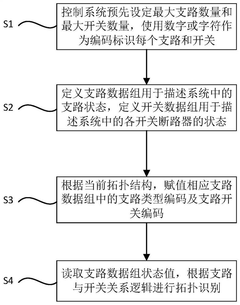
[0029] image 3 Shown is the specific embodiment 1 of the method described in this case, specifically comprises the following steps in the specific embodiment of the present invention:

[0030] S1: The control system pre-sets the maximum number of branches and the maximum number of switches, and uses numbers or characters as codes to identify each branch and switch;

[0031] The control system predefines the maximum number of branches that the system can access, such as branch 1 to branch n; defines the maximum number of switches, switch 1 to switch n;

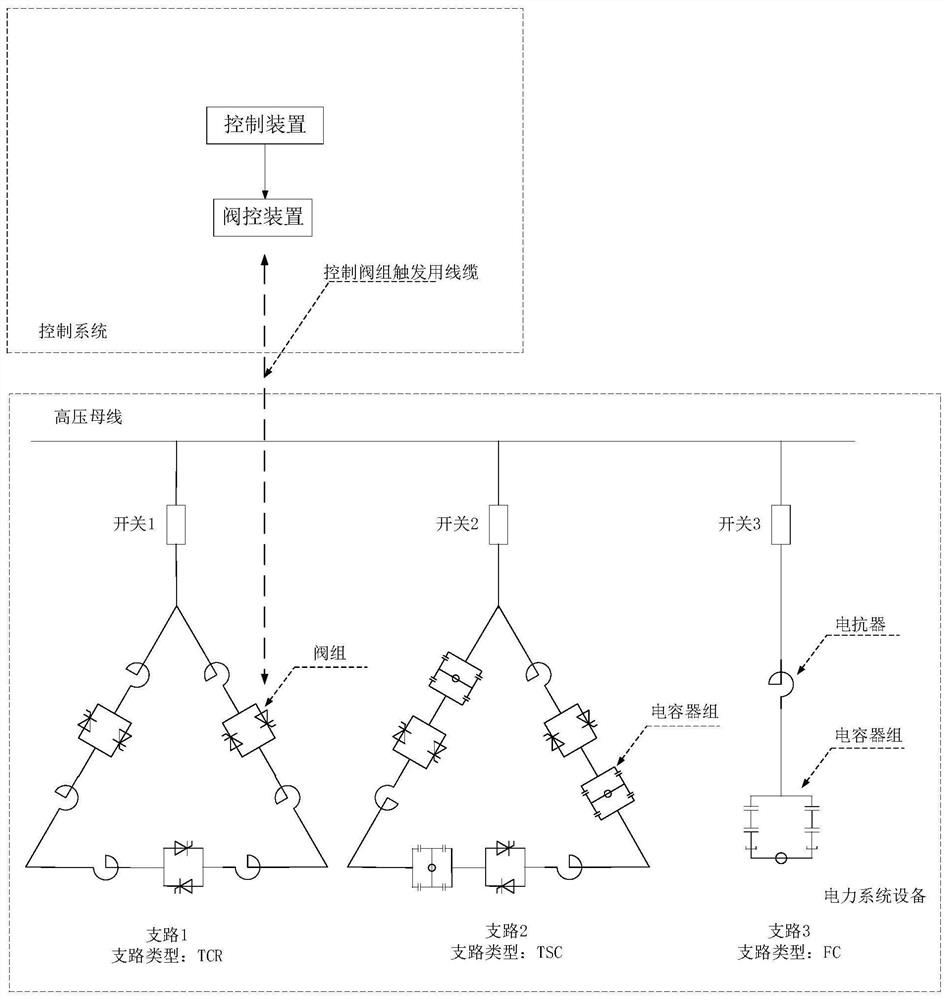
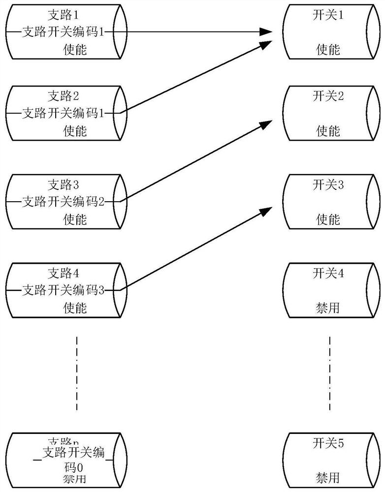
[0032] S2: Define the branch data group to describe the branch state in the system. The members of the branch data group include: branch code, branch type code, branch switch code, branch enable state, branch switch position ;

[0033] Define the switch data group to describe the state of each switch circuit breaker in the system, the switch data group includes: switch code, switch position, switch enabling signal;

[0034]...

Embodiment 2

[0040] Figure 4 Shown is the logic schematic diagram of the method described in this case, specifically comprises the following steps in the specific embodiment of the present invention:

[0041] S21: The control system presets the maximum number of branches and the maximum number of switches, and uses numbers or characters as codes to identify each branch and switch;

[0042] The control system predefines the maximum number of branches that the system can access, such as branch 1 to branch n; defines the maximum number of switches, switch 1 to switch n;

[0043] S22: Define a branch data group to describe the state of the branch in the system, the members of the branch data group include: branch code, branch type code, branch switch code, branch enabling state, branch switch position ;

[0044] Define the switch data group to describe the state of each switch circuit breaker in the system, the switch data group includes: switch code, switch position, switch enable signal; ...


PUM


Abstract

The invention discloses a static var compensator control system standardization method, comprising: the control system pre-sets the maximum number of branches and the maximum number of switches, uses numbers or characters as codes to identify each branch and switch; defines branch data The group is used to describe the branch state in the system; the switch data group is defined to describe the state of each switch circuit breaker in the system; according to the current topology, the branch type code and the branch switch code in the corresponding branch data group are assigned ; Read the state value of the branch data group, and perform topology identification according to the logic of the relationship between the branch and the switch. The present invention realizes that static var compensators of different topologies can use the same control system by defining the description mode of the control system for branch information.

Description

technical field [0001] The invention belongs to the field of power systems, and in particular relates to a method for standardizing the control system of a static var compensator under different topology conditions. Background technique [0002] Static var compensator (SVC) is often used in power systems to undertake tasks such as dynamically adjusting system voltage, suppressing system oscillation, filtering harmonics, and improving power quality. [0003] SVC is composed of control and protection system, thyristor control reactor (TCR) branch, thyristor switching capacitor TSC branch, and filter capacitor branch (FC) branch. The configuration of each branch is determined according to actual engineering requirements to form different topologies Structured SVC. [0004] The TCR branch is a thyristor-controlled reactor branch composed of valve groups and reactors, which can smoothly output inductive reactive power; the TSC branch is composed of valve groups, reactors, and ca...

Claims


Application Information

Patent Timeline
Patent Type & Authority Patents(China)
IPC IPC(8): H02J3/18
CPCH02J3/18Y02E40/30
Inventor 黄鑫李成博张磊周启文
Owner NR ELECTRIC CO LTD
Features
  • R&D
  • Intellectual Property
  • Life Sciences
  • Materials
  • Tech Scout
  • Unparalleled Data Quality
  • Higher Quality Content
  • 60% Fewer Hallucinations
Learn More