Full-automatic intelligent riveting device of motor rotor balance piece
A technology for motor rotors and riveting devices, applied in electromechanical devices, feeding devices, positioning devices, etc., can solve the problems of damaged motor rotor balance sheet, high error rate, slow speed, etc., and achieve simple and reasonable structure, riveting efficiency and precision high effect
- Summary
- Abstract
- Description
- Claims
- Application Information
AI Technical Summary
Problems solved by technology
Method used
Image
Examples
Embodiment 1
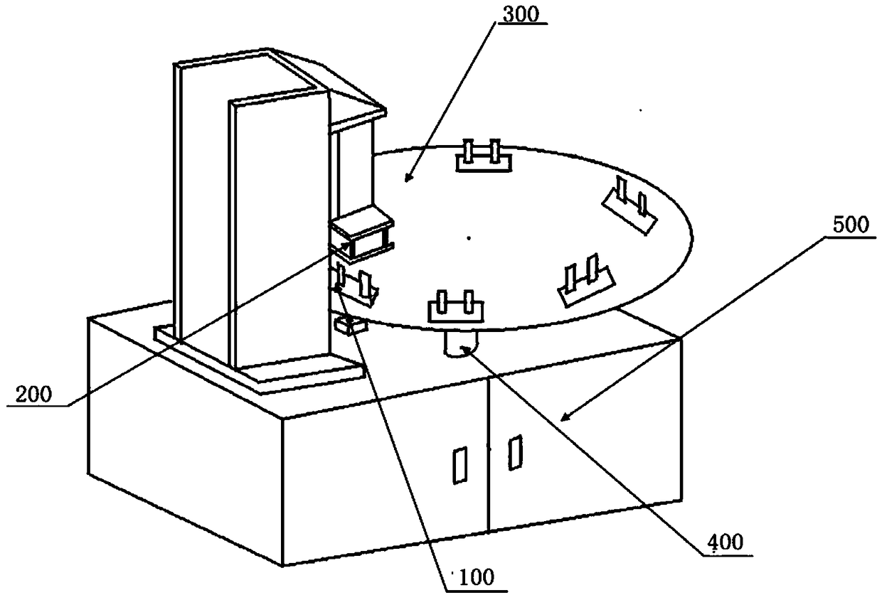
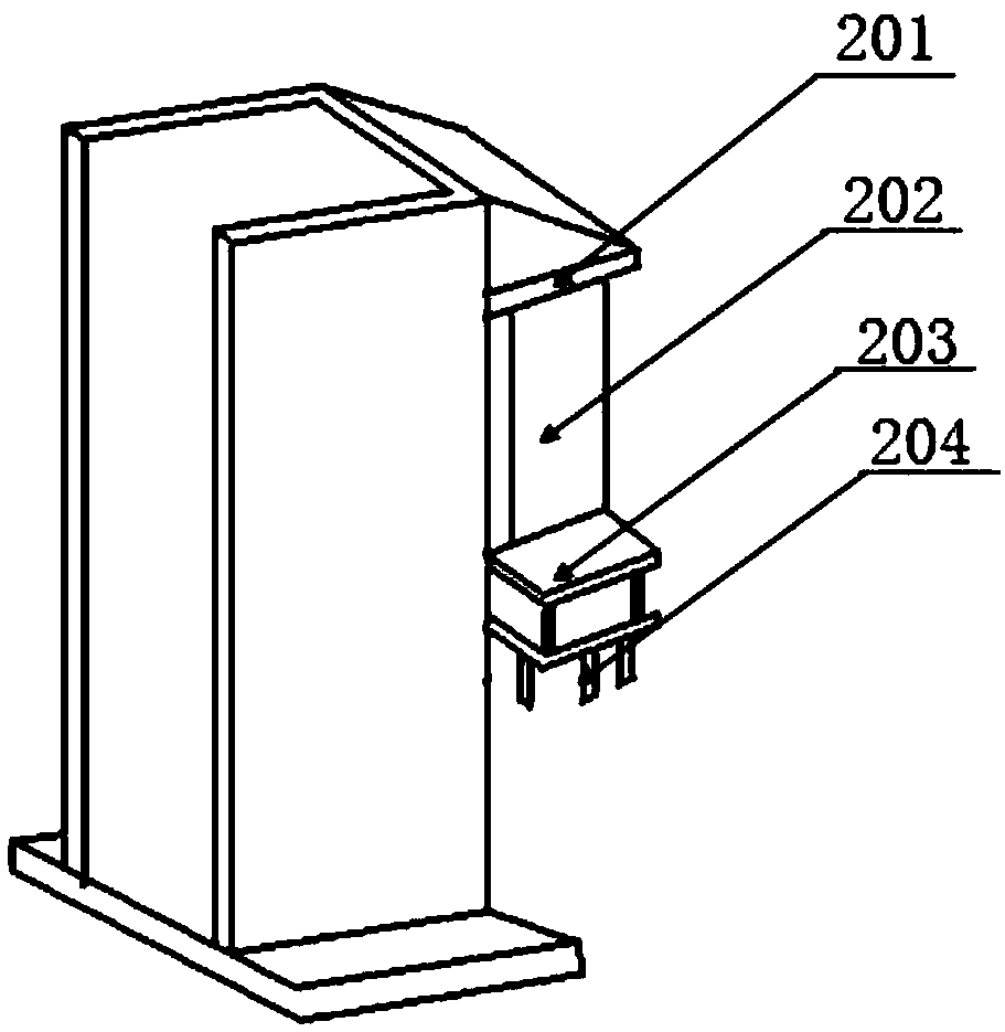
[0032] A fully automatic intelligent riveting device for motor rotor balance pieces, such as Figure 1~2 As shown, it is used for riveting the motor rotor and the balance plate, including a frame 400, a turntable 300, a plurality of positioning stations 100, a balance plate riveting mechanism 200 and a manipulator, wherein:
[0033] The turntable 300 is rotatably connected to the frame 400;
[0034] A plurality of positioning stations 100 are evenly distributed on the turntable 300 along the circumferential direction, and are respectively used to place the motor rotor;
[0035] The balance sheet riveting mechanism 200 is arranged above the rotation track of the positioning station 100, and is used for riveting the motor rotor and the balance sheet rotating to the bottom thereof;
[0036] The manipulator is used to place the motor rotor to the positioning station 100, place the balance sheet on the upper end of the motor rotor and remove the riveted motor rotor;
[0037] The ...
Embodiment 2
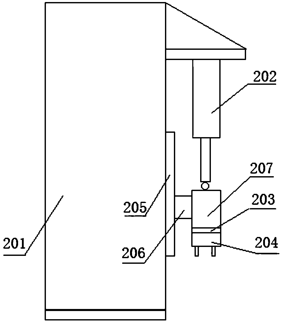
[0044] This embodiment is basically the same as Embodiment 1, the difference is that the balance plate riveting mechanism 200 in this embodiment also includes a guide rail 205 arranged on the riveting bracket 201, a slider 206 slidingly connected with the guide rail 205, and a slider fixed on the slider. The movable plate 207 on the block 206, the slide block 206 can slide up and down along the guide rail 205, and the cylinder rod of the hydraulic cylinder 202 is connected with the movable plate 207 (for example, the cylinder rod of the hydraulic cylinder 202 is hingedly connected with the top of the movable plate 207, such as image 3 As shown), the pressure sensor 203 and the pressure head 204 are sequentially arranged at the bottom of the moving plate 207 .
PUM
 Abstract
Description
Claims
Application Information
 - R&D
- Intellectual Property
- Life Sciences
- Materials
- Tech Scout
- Unparalleled Data Quality
- Higher Quality Content
- 60% Fewer Hallucinations
Browse by: Latest US Patents, China's latest patents, Technical Efficacy Thesaurus, Application Domain, Technology Topic, Popular Technical Reports.
© 2025 PatSnap. All rights reserved.Legal|Privacy policy|Modern Slavery Act Transparency Statement|Sitemap|About US| Contact US: help@patsnap.com


